Tuesday, March 6, 2012

0 Chevrolet LUV 1972-74 Axles Repair Manual

1972-74 Chevrolet LUV

DESCRIPTION
Axle housing is banjo type with removable differential carrier and semi-floating axle shafts. Ring and pinion gears are hypoid type in which centerline of pinion is set below centerline of ring gear. Differential case is one piece, two pinion design. The axle shafts are retained in housing by cone type roller bearing retainers at axle housing outer ends.
AXLE RATIO AND IDENTIFICATION
All LUV models are equipped with one type of rear axle assembly. Any differences in Removal and Installation or Overhaul procedures will be noted where they occur. To determine axle ratio, divide number of ring gear teeth by number of pinion teeth
REMOVAL AND INSTALLATION
Axle Shafts and Bearings
Removal - Raise vehicle and remove wheel and tire assembly. Remove brake drum, brake shoes and disconnect parking brake inner cable. Disconnect brake line from wheel cylinder and cover end to prevent loss of fluid and entry of dirt. From inboard side of brake backing plate, remove four nuts from the bearing holder through bolts. Pull axle shaft from housing.

Bearing Replacement - 1) Flatten locking tab of lock washer, then mount axel shaft in a vise, clamping vise jaws around lock nut. Using suitabl tool (J-24246) positioned on lub bolts, turn axle shaft loose from lock nut. Mount axle assembly in a press and remove lock nut, lock washer, bearing and holder, and brake backing plate. Remove oil seal from outboard side of bearing holder, then drive off bearing outer race with a drift.
2) To reassemble, install bearing outer race and grease seal into bearing holder using suitable drivers. Apply wheel bearing grease to bearing holder, rear axle tube, and bearing inner race. Insert the four through bolts into backing plate, making sure oil seal side of bearing holder is against backing plate. Place backing plate assembly over axle shaft, position bearing over axle shaft and press into bearing holder. Install new lock washer with dished side away from bearing, and thread lock nut onto shaft. Place lock nut between vise jaws, and using tool used during disassembly, tighten lock nut securely. Bend over portion of lock washer opposite locating tab to prevent lock nut from turning.

AXLE SHAFT SHIM SELECTION
Installation - 1) If both axle shafts were removed ,isert a .079 (2 mm) shim between bearing holder and axle tube flange of first axle shaft to be installed. Insert shaft into axle tube and install and tighten bearing holder-to-flange bolts. For the second axle shaft (or if only on shaft was removed), insert shaft without shims into axle tube until it comes in contact with thrust block in differential. Measure clearance between bearing holder and axle tube flange (see illustration).
2) Proper size shim for this location may be determined by adding .004" (.1 mm) to measurement just obtained. Select a shim or combination of shims, withdraw axle shaft, and install shims between bearing holder and flange face. Reinstall axle shaft and tighte four though bolts. Connect brake line to wheel cylinder, then install brake shoed, parking brake cable, and brake drum. Install wheel and tire assembly, adjust broken and bleed system.

DIFFERENTIAL CARRIER
Removal and Installation - Raise rear of vehicle, remove wheels and brake drums, and disconnect brake lines at rear wheel cylinders. Disconnect parking brace cable brackets at rear spring locations, remove four through bolts from each end flange, and partially with draw axle shafts from axle tubes. Disconnect propeller shaft from pinion flange and place out of way. Remove nuts attaching carrier to axl housing and remove carrier assembly To install, reverse removal procedure, making sure to refill axle with lubricant.

OVERHAUL
Disassembly
REMOVING PINION SHAFT LOCK PIN
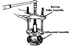
1) Mark side bearing caps for reassembly reference, remove nuts and bearing caps, then remove differential case assembly. NOTE - Keep right and left side bearing races with respective bearings. Remove differential side bearings from case using a suitable puller and adapter (J-22888 and J-81072). Record thickness of each side bearing and each shim pack, then place with appropriate bearing race.
2) Remove ring gear bolts and separate ring gear from case. Drive out pinion shaft lock pin using a long drift. NOTE - It may be necessary to remove caulking in lock pin using a 5mm drill. Remove pinion shaft using a drift, then withdraw thrust block, pinion gears, side gears, and thrust washers.
3) Remove pinion nut and pinion flange. Drive the pinion gear from carrier using a soft hammer or drift. Withdraw front pinion bearing and oil seal. Using a drift, remove pinion bearing races from carrier. Mount pinion gear in a press and remove rear pinion bearing and depth shim from pinion gear.

REASSEMBLY AND ADJUSTMENT
Drive Pinion Depth - 1) Install front and rear pinion bearing races into carrier bores, lubricate pinion bearings, and position in respective races. Install a suitable gauging plate (J-23597-7) and preload stud and pilot (J-23597-9) through pinion bearings and tighten nut snugly. Rotate bearings to insure proper seating, then tighten lock nut until 20 in. lbs. (25 cmkg) of torque are required to rotate new bearings, or 8-10 In. Lbs. (9.2-11.5 cmkg) are required to rotate used bearings.
TOOL SETUP FOR MEASURING PINION
DEPTH
2) Place mounting discs (J-23597-8) onto arbot tool (J-23597-1) and place assembly in position in side bearing bores. Install bearing caps. Mount dial indicator on arbor post, preload dial 1/2 revolution, then tighten indicator in this position. Position indicator plunder on gauge plate, slowly swing across until highest reading of gauge plate. Swing plunger off gauge plate and note indicator reading. Reading is the correct thickness of rear pinion bearing depth shim for a nominal to .101". An indicator reading of .000" or .001" requires shims of .100" and .101" respectively.
3) Examine head of drive pinion; pinion depth code is stamped by chemical ink and is the lower of three numbers. A "+" (plus) number indicates need for greater mounting distance (decrease shim thickness), while a "-" (minus) number indicates need for smaller mounting distance (increased shim thickness). See following chart to determine proper shim variation to compensate for plus or minus markings. NOTE - If no pinion depth code is present, pinion is "nominal" and no correction to dial indicator reading is required.

Pinion code                                        Correction Required
+10............................................ Subtract .005" (.13 mm)
+8.............................................. Subtract .004" (.10 mm)
+6.............................................. Subtract .003" (.08 mm)
+4.............................................. Subtract .002" (.03 mm)
+2.............................................. Subtract .001" (.03 mm)
0................................................ No Correction Required
-2............................................... Add .001" (.03 mm)
-4............................................... Add .002" (.05 mm)
-6............................................... Add .003" (.08 mm)
-8............................................... Add .004" (.10 mm)
-10............................................. Add .005" (.13 mm)
4) Place selected shim on drive pinion and press rear bearing on pinion. NOTE - Do not press on roller cage; press only on bearing inner race. Remove gauging tools from carrier.

Pinion Bearing Preload (W/ Solid Bearing Spacer) -  1) Place drive pinion and bearing spacer into carrier, then position original pinion shim and front pinion bearing over pinion gear. Install pinion flange and nut, tightening nut snugly. NOTE - Do not install oil seal at this time. Rotate bearing to insure proper seating, then tighten pinion nut to 190 ft lbs. (26.3 mkg). Wind a small amount of string (approximately 4-6 windings) around pinion flange. Using a pull scale, note pull scale reading required to rotate flange.

2) Reading should be approximately 13-17 lbs. (5.9 - 7.7 kg) for new bearings, or 8-10 lbs (3.6-4.5 kg) for reused bearings. If necessary to adjust preload, remove nut and pinion flange and remove or install shims behind front bearing. Shim are available in thicknesses of .003" (.08 mm), .005" (.13 mm), and .010" (.25 mm). NOTE -To increase preload, decrease shim thickness; to decrease preload, increase shim thickness. When correct preload is obtained, remove pinion nut and flange, install oil seal, then reinstall flange using a new pinion nut.
Pinion Bearing Preload (W/Collapsible Bearing Spacer) - 1) Place drive pinion and collapsible spacer into carrier, then install front pinion bearing and oil seal. Mount pinion flange on drive pinion, apply lubricant to pinion threads, install pinion nut and tighten to 85 ft. lbs. (11.3 mkg). Rotate pinion to insure bearings are seated, then wind a small amount of string (approximately 4-6 windings) around pinion flange. Using a pull scale, note reading required to rotate flange.
2) Continue tightening nut in small increments until pull required to rotate flange in 17 lbs. (7.7 kg) for new bearings or 7-9 lbs (3.2-4.1 kg) for reused bearings. CAUTION - Preload builds quickly. Nut should be tightened only in small increments and pull scale used after each small amount of tightening. If preload is exceeded, a new collapsible bearing spacer must be intalled.

Case Assembly - Install side gears and thrust washers in case. Position thrust washers 180 degrees apart, then roll gears into position making sure they are in alignment to allow installation of pinion shaft. Place thrust block between pinion gears and drive pinion shaft into position, making sure roll pin hole aligns with hole in case. Measure backlash between side gears and pinion gears; if greater than .003" (.08 mm), install selective thrust washers to bring backlash within specifications. Washers are available in thicknesses of .037" (.94 mm), .041" (1.04 mm), and .045" (1.14 mm). NOTE - Increasing washer thickness decreases backlash; decreasing washer thickness increases backlash. Install lock pin into pinion shaft and caulk end to prevent loosening. Install ring gear into position on case, apply Lactite to bolt threads, and install and tighten ring gear to case bolts in a diagonal sequence.

Backlash & Side Bearing Preload - 1) If original side bearings, differential case, ring and pinion, and differential case, ring and pinion, and differential carrier are being reused, the original shims may be reinstalled in their respective positions. If only new side bearings are being installed, measure new bearings with a micrometer and compare thickness with original bearings. If new bearing is thicker, SUBTRACT difference from shim pack. If new bearing is thinner, ADD difference to shim pack.
CHECKING  RING GEAR RUNOUT
2) If new bearings and/or differential case, ring and pinion, or differential carrier are being installed, new shims must be selected as follows: Install side bearings onto differential case, but do not install shims at this time. Mount case into carrier bores. Move ring gear tightly against carrier on ring gear side (away from pinion), and hold in this position. Using a feeler gauge, measure clearance between bearing and differential carrier on side opposite ring gear. Record clearance.
3) A predetermined dimension (.018" on 1972 models, .002" on 1973 and later model(s) is needed to establish proper preload. Therefore, ADD this dimension to clearance obtained in this step 2) for proper preload. This will give necessary combined total thickness of both shim packs. Divide the total dimension into two packs equals the difference between original shim packs.
4) Remove case from carrier, remove side bearings and install shim packs, then reinstall bearings. Install differential case into carrier, tapping carefully into place. Install side bearing caps in original positions, install and tighten attaching bolts. Measure run-out of ring gear (see illustration). If run-out exceeds .002" (.05 mm), correct by cleaning or replacement of parts.
CHECKING RING AND PINION
BACKLASH
5) Mount a dial indicator against ring gear teeth and measure backlash in three locations. Backlash should be .005-.007 (.13-.18 mm): if not, shims behind side bearings must be adjusted. NOTE - To maintain preload when backlash is adjusted, the total thickness of both shim packs must not be altered. Therefore, if it is necessary to increase one shim pack, the opposite shim pack must be decreased by the same amount. To increase backlash, right side bearing shim must be increased, and left side decreased. To decrease backlash, rigth side shim must be decreased, and left side increased. NOTE - Backlash changes approximately .002" (.05 mm) for each .003 (.08 mm) shim change. After adjustment, make gear tooth pattern check to insure correct assembly.


Monday, March 5, 2012

0 Courier 1975-77 Drive Axles Repair Guide

DESCRIPTION
This axle assembly incorporates a removable carrier differential, having a hypoid type ring and pinion gear set, with the pinion being retained in the carrier by a companion flange and nut. Semi-floating axles are secured in the housing by the axle shaft bearing retainers.

IDENTIFICATION
Only one type of axle assembly is used. Axle ratio for manual transmission models is 4.11-1 and for automatic transmission models is 4.65-1. This can be determined by dividing the number of teeth on ring gear by the number on the pinion gear.

REMOVAL AND INSTALLATION
Axle Shafts and Bearing
Removal - After removing complete brake assembly, including nuts securing backing plate and bearing housing-to-axle housing, slide axle shaft out of housing. Remove inner oil seal from axle shaft, spread locking tabs on lock washer, then using a suitable spanner (T72J-4252) remove lock nut and washer. Using a suitable puller (T72J-1225), remove bearing with housing from shaft. Remove bearing cup and outer seal from bearing housing.

Installation - Using suitable tool (T72J-1177), install new outer seal in bearing housing. Press or drive new bearing cup into retainer using suitable tool (T72J-4252-B). Install brake backing plate and bearing housing on axle shaft, then position bearing on axle shaft. NOTE - Insure bearing taper points in the right direction. Slide a suitable tool (T72J-4252-A) over shaft, place axle shaft on end in press, and press bearing into place. Install lock washer and nut, using a spanner to tighten nut. Install axle shaft and loosely assemble two bolts through bearing housing and axle housing flange. Mount a dial indicator to backing plate so axle end play can be measured. NOTE - If both axles have been removed, check end play of each shaft as it is installed. If end play is not to specifications, adjustment is made by using appropriate shims between axle housing flange and bearing housing. After correct end play is obtained, install and tighten as necessary, all remaining components.
FIG. 1 EXPANDED VIEW OF COURIER DIFFERENTIAL ASSEMBLY

DIFFERENTIAL CARRIER
FIG. 2 EXPLODED VIEW OF AXLE ASSEMBLY
Removal - Raise and support vehicle. Drain lubricant from differential, replace drain plug, then remove axle shafts as previously outlined. Mark drive shaft and companion flange at differential for reference at time of reassembly, then remove drive shaft. Remove carrier-to-housing retaining nuts, then remove ccarrier from housing.
Installation - Reverse removal procesure using a suitable sealer between the carrier and axle housing, and insure drive shaft-to-companion flange reference marks are aligned.

OVERHAUL
FIG. 3 CHECKING RING GEAR
BACKFACE RUNOUT
1) Remove differential carrier as previously outlined, then mount carrier assembly in a suitable holding fixture with ring gear facing upward. Mount a dial indicator to carrier housing and check ring gear runout for reference at time of reassembly. Also make a gear tooth contact pattern check. Refer to Rear Axle Gear Tooth Patterns in this section.
2) Punch mark differential bearing caps and adjusters for reference at time of reassembly. Remove adjuster lock plates. Loosen bearing cup nuts and back off adjusters using a suitable spanner (T72J-4076). NOTE - Adjuster on left has left hand thread. Remove nuts, bearing caps, and adjuster, keeping each bearing cap with its own adjuster.
3) Lift out differential assembly keeping each bearing outer race with its own bearing. To remove differential bearings, use a suitable puller (T70P-4221). Remove bolts and locks retaining gear to case, then remove ring gear. Drive out differential pinion shaft lock pin and remove pinion shaft and thrust block. Rotate pinion gears 90 degrees and remove them. Lift out differential side gears along with their trust washers.
4) Hold pinion gear companion flange and remove nut, then the flange. Remove drive pinion and rear bearing. NOTE - If required, use soft headed mallet to tap pinion gear from case, and guide pinion out to avoid damage to gear teeth. Remove collapsible spacer, oil seal and front bearing. Remove pinion bearing races from carrier using a drift in the slots provided. Remove bearing from pinion gear using a suitable tool (T72J-4630) and remove shim from pinion gear.

REASSEMBLY AND ADJUSTMENT
Case Assembly 1) If original ring and pinion gear set is being installed, use original shim between bearing and pinion head. If a new gear set is being installed, determine the size of shim to use in the following manner: Drive pinions may be stamped either "+1,2,3" or "-1,2,3", or they may be unmarked. Compare marks on tapered ends of old and new gears. Subtract the two number. Subtract the two number. A plus remainder means to install a thinner shim than the original. A minus remainder means to install a thicker shim than the original. If the  number is the same on both gears or if both gears are unmarked, use the original shim. NOTE - Shims are available in thicknesses from .120" to .135" (3.048 mm to 3.429 mm) in increments of .001" (.025 mm).
FIG. 6 INSTALLING DRIVE
PINION BEARING RACES
2) Using suitable driver (T72J-4616) install pinion gear bearing races. Install selected shim on pinion gear then install bearing on pinion using suitable tool (T70P-4625) and a press, Install pinion gear and bearing in carrier followed by the collapsible spacer, front bearing, oil seal and companion flange. Install, but do not tighten, companion flange nut.
3) Using an inch pound torque wrench on companion flange nut, rotate pinion gear and note drag o foil seal. Remove inch pound torque wrench and start tightening nut. As nut is tightened, keep checking rotating torque with inch pound torque wrench. When nut is tightened to 145 foot pounds (20.0 mkg) minimum and rotating torque is 11.3-15.6 INCH (20.0 mkg) pounds (13-18 ckg) plus the oil seal drag, preload is correct. NOTE - If preload is exceeded, install new colllapsible spacer and repeat procedure. Do not back-off nut to obtain preload.
Differential Assembly - Reverse disassembly procedure noting the following checks and adjustment.
FIG. 7 CHECKING PINION-TO-GEAR
BACKLASH
Side-to-Pinion Gear Backlash - After installing side and pinion gears, insert pinion shaft, without thrust block, into its proper position. Chec side-to-pinion gear backlash. If backlash exceeds .008" (.20 mm), refer to table and install appropriate side gear thrust washers to obtain the correct backlash. Remove pinion shaft, then reinstall it with the thrust block.
                      Side Gear Thrust Washers 
I.D. Mark                                  Thickness
6..............................................  .063" (1.6 mm)
7..............................................  .067" (1.7 mm)
8..............................................  .071" (1.8 mm)
Ring-to-Drive Pinion Gear Backlash - After differential is completely assembled and installed in carrier, snug bearing cap nuts. Turn adjusters, using spanner, until bearings are properly seated and end play is eliminated with a slight amount of ring-to-drive pinion gear backlash. Slightly tighten one bearing cap nut on each side. Mount dial indicator to carrier flange with indicator plunger set at a right angle to rign gear teeth. Check ring-to-drive pinion gear backlash of four or five points around ring gear. Turn both adjusters equally to obtain specified. Proceed by setting differential bearing preload.
FIG. 8 CHECKING DIFFERENTIAL BEARING PRELOAD

0 Colt 1975 Drive Axle Repair Manual

DESCRIPTION
Rear axle is of the banjo type, utilizing the removable carrier style differential. Light weight construction joins split tublar housings for each side with center covers welded to axle housing. Final drive is of the hypoid style. Axle shafts are semi-floating type supported with bearings at their respective ends in axle housing. Bearings are fitted to axle with pressure type bearing retainers. Pinion bearing preload, side bearing preload, and pinion depth adjustments are made with shims while differential side gears are adjusted with spacers.

AXLE RATIO AND IDENTIFICATIONS
Colt does not attach any tag or other easily identified item to the rear axle housing. Colt vehicles do however, utilize only one kind of rear axle assembly. Removable carrier.
NOTE - There may be two types of differential cases, side gears, and pinion gears. When replacing these components ensure correct parts are selected.

                         Differential Gear Radio
Application                                               Axle Ratio
97.5"............................................................  3.889-1
121.7"
     Gt and Formula S .................................  3.889-1
     All Others............................................... 3.545-1

REMOVAL AND INSTALLATION
Axle Shafts and Bearings
FIG. 1 MEASURING AXLE SHAFT
DEFLECTION
Removal - 1) Raise and suitable support rear axle housing so rear wheels clear ground. Remove rear wheel and brake back plate nuts, then disconnect wheel cylinder brake line. Fix suitable puller set (CT-1003 and C-637) to lug studs and work slide hammer until axle shaft is free to be withdrawn. Set brake back plate with parking brake attached out-of-way. Using suitable tool (C-637 with hook) remove axle oil sea.
2) To remove axle bearing proceed as follows. Grind down bearing retainer at one point until retainer thickness is .04-.06" (1.0-1.5 mm), then chisel ground portion and remove retainer. Using suitable bearing puller or press (CT-1120) remove bearing from axle.
3) Using a dial indicator, inspect axle shaft deflection in three spots (see illustration). Replace axle shaft if specifications are exceeded.
                          Axle Shaft Deflection Table
Application                  Std. Value                    Service Limit
Point "A".....................  0-.004".............................. .004"
                                       (0.-.10mm)......................... (.10 mm)
Point "B"...................... 0-.002"............................... .002"
                                       (0-.05 mm)........................... (.05 mm)
Point "C"...................... 0-.08".................................  .08"
                                       (0-2.0 mm)............................(2.0 mm)
FIG. 2 EXPANDED VIEW OF AXLE SHAFT
ASSEMBLY
4) Rear axle bearing should be replaced when bearing noise is detected, when bearing axle free play exceeds .014-.016" (.36-.41 mm) or if bearing radial free play exceeds .001-.002" (.03-.04 mm) at approximately 11 lbs. (5.0 kg) measuring force.
5) Inspect wheel hub bolts for tightness and bearing outer retainer for deformation, replace defective parts as necessary.

Installation - 1) Fit outer bearing retainer flat side against shaft splined end, then install bearing and inner bearing retainer. Seat bearing retainer with smaller chamfered side directed to the bearing. NOTE - Ensure bearing is completely steated.
2) Lightly coat lips of oil seal and using suitable oil seal installer (DT-1007B and CT-1008) fit axle shaft oil seal in rear axle housing.
3) Using packings and shims in proper sequence, set clearance between bearing and outer bearing retainer to .00-.01" (.0-.25 mm).
4) Carefully insert axle shaft assembly into axle housing using care not to damage seal. Slightly turn axle shaft until splines line up with differential side gears. Align packing oil holes with outer bearing retainer and tighten bearing retainer to axle housing flange. Connect brake line to wheel cylinder and bleed air out from system.

DIFFERENTIAL CARRIER
FIG. 3 REMOVING DIFFERENTIAL
GEAR HOUSING
Removal - Drain oil from rear axle differential housing, then disconnect propeller shaft. Pull out both rear axle shafts approximately 2 1/2". Remove differential gear carrier It may be necessary to tap outside of housing to break gear carrier loose.
Installation -Lightly coat each bearing and gear with oil. Apply sealing compound on packing and axle housing with nuts and tighten. Fill differential gear housing with .96 quart of suitable multi-purpose gear oil (API GL-5).

OVERHAUL
Disassembly
FIG. 4 REMOVING DIFFERENTIAL SIDE
BEARINGS
Differential Gear Assembly - 1) Remove bearing carrier cap and lever gear case assembly from housing. Using suitable bearing puller tool (C-293-P and C-293-39) pull differential side bearing. Keep rigt and left bearings and shims in sequence for reassembly.
2) Remove ring gear lock plate tabs and loosen bolts in diagonal sequence, then remove ring gear. Drive out pinion shaft lock pin from ring gear back side using a punch; pull out pinion shaft and pinion. Pinion side gears and spacers are now accessible. Note placement of pinion side gear and spacers and ensure they are reassembled in same position.

FIG. 5 REMOVING DRIVE PINION BEARING
Drive Pinion Disassembly - 1) Hold end yoke with suitable tool (C-3281) and remove lock nut, then remove end yoke. Using a wheel puller, force out drive pinion with adjusting shim, rear inner bearing race, spacer and preload adjusting shim.
2) With suitable bearing puller (C-293-P and C-293-39) remove rear bearing inner race and at same time, pull off drive pinion adjusting shim. Using suitable drift, remove front drive pinion bearing outer race and oil seal. Repeat some procedure to remove bearing outer race.
FIG. 4 REMOVING DIFFERENTIAL SIDE BEARINGS
FIG. 6 REMOVING DRIVE PINION BEARING OUTER RACE
FIG. 7 EXPANDED VIEW OF COLT SEPARATE HOUSING REAR AXLE ASSEMBLY


INSPECTION
Check differential gears for correct tooth contact and replace gears if wear is excessive. Inspect bearing faces for roghness or score marks and replace, if necessary, bearing assembly. Ensure splines of side gears and rear axle shafts fit correctly. Check clearance between pinion gears and pinion shaft, if wear is excessive, replace components.
NOTE - To check gear tooth contact using point impression method, refer to beginning of this section.

REASSEMBLY AND ADJUSTMENT
FIG. 9 MEASURING CLEARANCE BETWEEN
SIDE BEARING AND GEAR CARRIER
Case Assembly - 1) Install thrust washers (spacers) behind side gears in their original position and assembly pinion and side gears in differential. Insert both pinion gears, with pinion washers attached, so they mesh with side gears. It may be necessary to slightly rotate pinions to achieve desired meshings. Insert drive pinion shaft.
2) Check pinion and side gear backlash as shown in illustration. If backlash is beyond 0-.003" (0-.08 mm) adjust by selecting a side gear thrust washer (spacer) of correct size. If backlash is to be adjusted, ensure right and left sides are equally shimmed.
3) Thoroughly clean all dirt from ring gear mounting surface of differential case. Install bolts and lock washers. Tighten bolts alternately in a diagonal sequence and bend over lock tabs. Ensure lock washers are in contact with case rib after final torque has been perforemed.

Drive Pinion - Using a suitable drift and hammer or a press, seat front and rear bearing outer races into gear carrier ensuring that outer races do not cock. Ensure bearing races are completely seated before proceeding. Install shim between drive pinion and rear bearing. Using suitable bearing installer (CT-1075) press bearing onto drive pinion shaft. If drive pinion and bearings are scheduled to be reused, shims should be replaced with new ones of same thickness. In instances where the gear set is to be replaced, install new shims that  are the same thickness as used shims on drive pinion. NOTE - When determining the desired thickness of shim pack, amount of compression the desired thickness of shim pack, amount of compression (sinkage) of shim pack and wear of the bearing (where old bearing is reused) must be taken into consideration

Drive Pinion Depth - Install drive pinion spacer, front bearing, washer, end yoke and washer in order of removal. Fit pinion shaft retaining nut and slowly tighten nut, continuously checking, until pinion bearing preload is 6-9 INCH lbs. (7-10 cmkg) with oil seal not installed. Place suitable cylinder gauge on inside bearing pedestals of gear carrier housing. Place a block gauge on top end of drive pinion and slip a feeler gauge between the two gauges to obtain the correct clearance. The clearance between gauges should be .0118" (.300 mm). This is the standard height and any deviation from this height will be marked on the head of the pinion shaft and side of ring gear. To calculate the correct pinion height, add or subtract the variation value from the standard height. NOTE -Stamped values are in hundredth millimeters. Add or subtrace the correct amount of shims as necessary.

Pinion Bearing Preload - This adjustment must be perforemed after the setting of the drive pinion depth. Remove end yoke and insert the bearing preload adjusting shim between pinion spacer and bearing, then tighten end yoke to 9-11 INCH lbs. (10-13 cmkg). In addition to the preload adjusting shims there are spacers available to provide proper adjustment. After finishing adjustment of drive pinion bearing preload remove the end yoke and apply a thin coat of grease to outer surface of oil seal, then drive seal into position in gear carrier. After greasing oil seal lip, insert end yoke and tighten nut.

Side Bearing Preload - Fit each side bearing into differential case leaving shims out; use suitable tool (CT1102) for this procedure. Ensure side bearings are completely seated before proceeding. Install differential case assembly on gear carrier, then calculate the clearance between side bearing outer race and bear carrier as shown in illustration. After obtaining clearance add .002" (.05 mm) preload figure to each side. Insert shims equally on both sides. Align gear carrier and bearing cap index marks, then tighten cap retaining bolts.

Ring Gear Deflection - Attach a dial indicator to back side of ring gear and measure deflection. If ring gear has excessive deflection, correct position of the assembly in relation to differential case and again perform measurement. Replace ring gear or differential case as necessary.

Drive Pinion Backlash - Measure backlash of drive pinion in at least four different spots on ring gear with drive pinion securely fixed in final position. Set up a dial indicator on ring ring gear teeth edges. If measured backlash is greater than .005-.007" (.13-.18 mm), shift shims from ring gear side to back of the ring gear to obtain proper backlash. If the measure value is less than standard value, reverse the moving of shims as stated above. Side bearing shims are available in various thicknesses.
NOTE -Check gear tooth contact using paint impression method described at beginning of this section.

Final Inspection and Assembly - Lightly coat each gear and bearing before and during reassembly with gear oil. After installing each component, ensure all rotating parts are free to move smoothly. Install differential gear assembly to axle housing after applying sealing agent and tighten gear carrier mounting nuts in diagonal sequence.


Sunday, March 4, 2012

0 Capri II 1976 Drive Axles Repair Manual

Models Covered 

  • Capri II (1976)
NOTE - The use of collapsable spacer to set drive pinion bearing preload, as described in this story, has been in effect since January 1974. Models prior to that used a selected spacer.

DESCRIPTION
An integral type housing, hypoid design, with centerline of pinion set below centerline of ring gear. Semi-floating axle shafts are retainer at axle housing by ball bearings and a bearing retainer at axle housing outer ends. All adjustments are performed using selective fit shims and gaskets.
REMOVAL AND INSTALLATION
Axle Shafts and Bearings
1) Remove brake drum retainers and remove brake drum. Remove bolts securing bearing retainer plate to axle housing. These bolts are accessible through holes in axle shaft flange. Pull axle shaft and bearing assembly out of axle housing.
2) Loosen inner retainer ring by nicking it deeply with a cold chisel in several places. It will then slide off easily. Press bearing and seal assembly from axle shaft using arbor press and suitable tool to hold and support bearing.
3) To install, inspect housing and axle shaft and lightly coat wheel bearing bore with axle lubricant. Place bearing retainer plate on axle shaft, and press new wheel bearing on shaft using suitable tool. NOTE - Do not attempt to press on both bearing and inner retainer of the same time.
4) Using suitable bearing installation tool, press bearing inner retainer ring on shaft until retainer seats firmly against bearing. Insert axle shaft into housing and engage splines. Top shaft into position. Install bolts securing bearing retainer plate and install brake drum and retainers.

REAR AXLE ASSEMBLY
1) Raise vehicle and remove wheels. Mark propeller shaft for proper alignment and disconnect from drive pinion flange. Release parking brake; then remove locknut and adjusting nut from handbrake cable and disconnect cable from relay lever. Disconnect line from brake hose.
2) Raise and support center of rear axle and disconnect shock absorbers from axle. Remove rear axle support. Remove two stabilizer bar retaining clamps from rear axle housing. Remove rear spring "U" bolt nuts and detach bolts and plates. Lift axle assembly and remove from vehicle.
3) To install, lift rear axle assembly into position on spring, being sure that it is correctly located over spring pilot bolts. Align and loosely fit propeller shaft to drive pinion flange. Fit "U" bolts  over axle, slide on lower plate, install new locknuts and tighten.
4) Using a suitable tool, hold rear stabilizer bar onto mounting pads on axle housing and install retaining clamps. Insert retaining clamp bolts, check for binding and tighten. Raise center of rear axle and install shock absorbers. Remove axle support
5) Reconnect brake line to brake hose and handbrake cable to relay lever on rear axle housing. Adjust nut until relay lever is just clear of stop, tighten locknut. Tighten driveshaft-to-pinion flange bolts and bleed rear brake system. Fill rear axle housing with lubricant, mount rear wheels and lower vehicle.

OVERHAUL
Differential Case
FIG 1. CHECKING DRIVE PINION
DEPTH
Disassembly - 1) Raise vehicle and remove wheels and axle shaft assemblies. Mark propeller shaft for correct realignment and disconnect from pinion flange. Remove ten cover attaching bolts, cover and gasket and drain rear axle oil. Discard gasket and thoroughly clean cover.
2) Remove differential bearing caps and mark caps for correct repositioning. Lift differential out of axle housing using two pry bars. Remove tapered roller bearing from each side of differential assembly using a suitable puller. Remove adjusting shims from differential housing. Remove ring gear attaching bolts and ring gear from differential assembly.
3) Using a suitable drift, remove lock pin securing differential pinion shaft in case and remove pinion gears, side gears and adjusting shims. Using an INCH pound torque wrench on drive pinion retaining nut, note torque required to turn drive pinion gear. Remove torque wrench, hold pinion flange and remove drive pinion retaining nut. Remove pinion flange using a suitable puller, then remove pinion. Remove large bearing from drive pinion using press and suitable fixtures. Remove outer pinion bearing and seal from axle housing using a suitable drive. Remove bearing races from axle housing using a drift.

Reassembly - 1) Install pinion bearing races into axle housing. Set pinion depth as follows: Pinion cross bar of pinion depth gauge tool (T70P-4133) and side bearing in rear axle housing. Install bearing caps (number to number) and tighten attaching bolts. Loosen bolts and retighten finger-tight. Preload side bearing by expanding depth gauge crossbar by holding bar and rotating nut. Seat side bearing and check that side bearing are still preloaded. Do not over expand cross bar. Tighten bearing attaching bolts.
2) Install dummy pinion (part of special tool) into axle housing with pinion bearing but no shims. Lightly lubricate bearings and tighten tool until correct pinion bearing pre-load is obtained. Rotate dummy pinion several times to insure seating of bearings. It is essential that the torque reading be recorded and followed for further adjustment of drive pinion. This torque must also be checked after installation of drive pinion with collapsable spacer.
FIG 2. EXPLODED VIEW OF OF CAPRI II DRIVE AXLE ASSEMBLY
(CLICK TO ENLARGE)

3) Mount dial indicator on mounting brakcet and set to zero on dummy pinion. Slowly rotate dial indicator over cross bar of tool and read total deflection of pointer. This reading gives the exact thickness of the shims to be used. When pinion is marked "-1" or "-2" this amount must be added to indicator reading. When gear is marked "+1" or "+2" this amount must be subtracted from reading to obtain correct shim thickness. Using a micrometer, select a shim of the determined thickness.
FIG 3. MEASURING SIDE GEAR
CLEARANCE
4) Position shim(s) on pinon and press on large tapered roller bearing using a press and suitable fixture. Position differential side gears, with one shim each, in differential case. The grooved side of shim must be towards side gear. Position differential pinions and thrust washers between differential side gears. Push the differential pinion shaft into position in case, taking care to align locking pin holes. Measure play of each side gear using a feeler gauge. If side play is not to specifications, install new shims. Secure differential pinion shaft with a locking pin.
5) Position ring gear on differential case and locate with bolts. Pull ring gear evenly into position with bolts. Remove old bolts and install new bolts and tighten. To determine total play of differential case in axle housing. Press tapered roller bearing onto differential case without shims after first inspecting bearings for damage. Install pressure blocks (part of tool T70P-4136) into axle housing on each side of differential case and install differential case and bearings in axle housing. Install bearing caps (number to number) and tighten attaching bolts. Now, loosen bolts and tighten finger tight.
6) Tighten pressure spindle (tool T70P-4136) to a torque of 43 INCH lbs. Rotate differential several times and recheck torque. Mount dial indicator on rear axle housing so that feeler contacts inner side of ring gear flange and zero indicator. Place pressure spindle into other side of housing and tighten to 43 INCH lbs. Read and note amount of indicator deflection and record as total play of differential case in rear axle housing. Loosen pressure spindle, tilt dial indicator to side and remove differential, pressure spindle and pressure blocks.
FIG 4. DIFFERENTIAL SET-UP, PRESSURE BLOCK AND SPINDLE INSTALLATION

7) Install inner bearing on drive pinion gear along with collapsable spacer. Install drive pinion gear, outer pinion bearing, new oil seal and flange into housing. Install new pinion flange nut and hold pinion flange using a suitable holding fixture.
8) Slowly tighten nut. Keep checking pinion gear rotating torque (using INCH pound torque wrench) until rotating torque is equal to that noted during disassembly. Tighten on additional 2-4 INCH pounds torque for friction of new oil seal. Pinion nut torque should be to specification when pinion rotating torque is correct, install new collapsable spacer and repeat procedure.
9) To determine differential case bearing shim thickness: Place pressure blocks back into axle housing and place differential case with bearing races into axle housing. Install bearing caps, tighten screw, then loosen and tighten finger tight. Using pressure spindle, press differential housing with a torque of 43 INCH lbs. away from drive pinion. Rotate pinion several times. Position feeler of dial indicator gauge at right angle to one tooth of ring gear. Measure tooth flank backlash at 4 points, each time turning gear two bolt heads further. Deviation of tooth flank backlash must not exceed .002" (.05 mm). Insert pressure spindle into other side of axle housing and screw in slowly until there is the specified value of tooth flank backlash.
10) Position dial indicator so that feeler contacts ring gear flange and zero indicator. Insert spindle into other side of axle flange and zero indicator. Insert spindle into other side of axle housing and torque to 43 INCH lbs. Read and record indicated deflection on indicator as ring gear back side shim thickness. Remove pressure spindle, differential case and pressure from axle housing.
FIG 5. MEASURING RING GEAR
BACKLASH
11) To calculate shim thickness, first take the value of differential case total play obtained in step 6) and add to this value a value for ring and pinion backlash which will give an even number. For example, if total play is .0529" (1.344 mm), add for preload the value of .0021" (.056 mm) (preload value selected from specified range) to obtain .055" (1.40 mm). Next, take the value for ring gear back side shim thickness, measured in step 10) and subtract .005" (.13 mm) from this value. For example, if ring gear back side shim thickness is .025" (.64 mm), subtract .005" (.13 mm) to obtain .020" (.51 mm). Now subtract value just obtained (.020" or .51 mm) from total play value obtained above (.055" or 1.40 mm) to obtain ring gear face side shim pack, in this example .35" (.89 mm).
12) Remove differential case bearings and position required shims on differential case. Using suitable tools, press tapered roller bearing onto differential case after checking bearing for damage. Insert differential case in axle housing and position bearing caps as previously marked. Coat bolt threads with sealing compound and insert bolts.
13) Position dial indicator feeler in a vertical position on one ring gear tooth and check that pinion to ring gear backlash is to specifications. If not, differential must be removed and shims adjusted. If backlash is too great, remove shims from ring gear face side and transfer to ring gear back side and vice versa. Do NOT increase or decrease number of shims, but only interchange between one side and the other.
14) Finally check gear tooth contact pattern and adjust as necessary to obtain correct pattern. Position housing cover and new gasket on axle housing and install and tighten bolts. Attach parking brake operating lever to rear axle housing and correct return spring to bracket on housing. Install rear brake assemblies on axle housing and correct parking brake cable to brake assemblies.


0 BMW 1969-74 Drive Axles Repair Manual

1969-74 BMW SPLIT HOUSING

MODELS COVERED:

  • 2500 Series (1969-70)
  • 2800 Series (1969-70)
  • 3000 Series (1971-74)
DESCRIPTION
HALF SHAFT CONSTANT VELOSITY JOINT
Differential has hypoid type ring and pinion gear set, and may have one of two cluch pack type limited slip units. Left side of housing is the housing cover and must be removed to expose carrier assembly. Cover incorporates a ball bearing and oil seal for left axle flange, and a bearing cone for the left differential carrier bearing. Right carrier bearing and seal are incorporated in housing. The pinion gear is supported by roller bearings and preload is maintained by a collapsible spacer.

AXLE RATIO AND IDENTIFICATION
Ring and pinion gear set with Klingelnberg tooth design, can be identified by the lettter "K" stamped on the head of the pinion gear; Gleason teeth are noted by an "H" or "F" stamping. To determine axle ratio, divide number of ring gear teeth by number of pinion gear teeth. The number of teeth on ring and pinion, and the code for limited slip differential (S40), is stamped on right side of differential housing.

REMOVAL AND INSTALLATION
DRIVE SHAFTS AND UNIVERSAL JOINTS
Remove drive shaft after removing retaining bolts from axle and half shaft flanges. Remove cover from joint housing and snap ring from end of drive shaft. Remove clamps from boot then press drive shaft joint. Remove dust boot-to-joint surfaces, and install seal cover after packing joint with suitable grease.
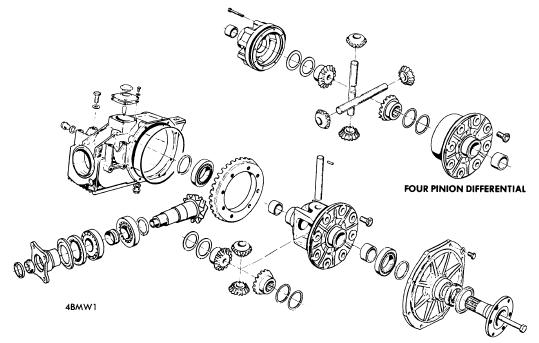
STANDARD TWO PINION DIFFERENTIAL ASSEMBLY 
LIMITED SLIP DIFFERENTIALS (TYPICAL)


AXLE SHAFTS AND BEARINGS
PULLING AXLE DRIVE FLANGE
Raise and support vehicle. Remove wheel, drive shaft, axle flange retaining nut, and using a puller, if required, remove axle flange. Using soft headed mallet; drive axle shaft out of housing. Drive out bearings and seals, then remove spacer sleeve and shim. To install, reverse removal procedure noting the following: Install outer bearing then determine distance between outer races of inner and outer bearings. Measure spacer and shim, then install spacer and a suitable shim that will obtain the specified wheel bearing end play. Pack bearings and new seals with suitable grease, then complete installation procedure.

AXLE FLANGE, SEAL AND BEARING
PULLING AXLE DRIVE FLANGE BEARING
Remove drive shaft. Hold axle flange using suitable tool (7012) and remove flange retaining bolt. Using suitable puller (7011-2) remove axle flange. Pry out oil seal and if required, remove ball bearing on cover side, using suitable puller. To install, reverse removal procedure after packing bearing and/or filling between sealing lips of seal with grease. Install seal flush with housing or cover bore.
NOTE - Differential carrier can be removed from housing with differential assembly installed in vehicle. After removing axle flange, follow Differential Carrier, Disassembly and Overhaul procedure, in this story.

DIFFERENTIAL ASSEMBLY
Remove propeller shaft and drive shafts, tie drive shafts up out of way. Support differential and remove bolts securing it to front brackets and rear support. Remove differential assembly. To install, reverse removal procedure, insuring rear support is stress free when installed.

OVERHAUL
DISASSEMBLY
CHECKING RING GEAR BACKLASH
Differential Assembly - Remove differential assembly as previously outlined and mount assemly in suitable holding fixture. Drain oil and mark pinion shaft and companion flange for reassemly reference. remove inspection hole cover, mount dial indicator in one cover bolt hole and check ring gear backface runout and ring-to-pinion gear backlash. Check gear tooth contact patter. NOTE - Refer to Rear Axle Gear Tooth Patterns in this section. Remove axle flanges and side cover, then remove differential carrier assembly. Proceed as follows for standard or limited slip differential carrier disassembly.

Standard Differential Carrier (Two Pinion Type) - Remove carrier bearings using suitable puller (Rolex LM 503349). Separate ring gear from carrier. Drive out pinion shaft lock pin, remove pinion gears shaft and pinion gears, then remove side gears with shims and thrust washers.

Limited Slip Differential Carrier - Remove carrier bearings using suitable puller (Rolex LM 503349). remove bolts securing case-to-ring gear flange (Type 1), or cover-to-case (Type 2), insert case and lift case off clutch and gear assembly. Separate ring gear from flange. Remove clutch components. Lift off hub, remove side gear and one set of pinion gears. Repeat procedure for other half of case.

CHECKING PINION GEAR PRELOAD (TYPICAL)
Drive Pinion Gear - 1) Remove differential carrier as previously described, then check pinion bearing preload using an inch pound torque wrench. Remove pinion flange nut lock ring and using a suitable tool (7012) hold flange and remove nut.
2) Press pinion gear out. through flange and housing, then remove oil seal and front roller bearing. Using suitable puller set (6053), remove pinion bearing outer cones from housing.

REASSEMBLY AND ADJUSTMENT
DRIVE PINION GEAR ASSEMBLY
Differential Assembly - Reverse disassemly procdure noting the following checks and adjustments.
Drive Pinion Bearing Preload - 1) If original ring and pinion gear set is being installed and gear tooth pattern and pinion bearing preload was satisfactory at time of disassembly, install drive pinion gear using original shim and a new collapsable spacer. If a new gear set is being installed, determine correct size of shim to use in the following manner: Drive pinion gears may be stamped either "+1,2,3, etc" or "-1,2,3, etch". Compare marks on tapered ends of old and new gears. Subtract the two numbers. In relation to original new gears. Subtract the two number. In relation to original shim, a plus remainder means a thinner shim is required, a minus remainder means a thicker shim is required.
2) Remove then reinstall pinion gear, using new shim(s), collapsable spacer, and seal as required. Install compnion flange and nut and tighten nut to obtain specified drive pinion bearing preload. NOTE - If preload exceeded, new collapsible spacer must be installed, and this procedure is repeated

CHECKING SIDE-TO-PINION GEAR
BACKLASH (TYPICAL)
Side-to-Pinion Gear Backlash (Standard Differentials) - Install two pinion gears with shaft and one side gear. Mount dial indicator to carrier so plunger contacts side gear. Force side gear hard against pinion gears, zero indicator, then force side gear hard against case. With proper shim and thrust wahser, backlash should be as specified, and preload of all three gears should not exceed specified value. Repeat procedure on opposite side (with second set of pinion on four pinion type), then retain side gears pressed outward against carrier so axle flange retaining bolts can later be installed.

MEASURING TYPE 1 CLUTCH
ASSEMBLY
Clutch Assembly End Play (Type 1 Limited Slip Differential) - Assemble clutch assembly without ring gear or case. Apply 220 psi (15.5 kg/sq. cm) to one end of assembly. Measure depth of case. If clutch assembly-to-housing end play is not to specifications, adjust by using thicker or thinner inner cluch disc.

Clutch Assembly End Play (Type 2 Limited Slip Differential) - Without using the four small diameter thrust washers, two small spring washers, or two large spring washers, assemble clutch assembly in housing. Compare depth of housing cover thrust surface and thickness of large spring washers, to distance between edge of housing and outer clutch disc. Install suitable large spring washers to obtain specified end play. NOTE - If excessive end play exists, thicker outer clutch discs may be installed.

MEASURING TYPE 2 CLUTCH
ASSEMBLY
Checking Pinion Gear Torque (Limited Slip Differentials) - With differential carrier assembled, install axle flanges in carrier. Clamp one flange in vise and using and INCH pound torque wrench (Type 1), or foot pound torque wrench (Type 2), turn other flange. If rotating torque of side and pinion gears is not to specifications, install thicker or thinner case cover-to-clutch assembly thrust washers.

Differential Bearing Preload - Install one shim behind carrier bearing outer cone in side cover. Install bearing cone using suitable tool (6053). Install drive flange bolt, without flange, so it contact pinion gear shaft. Install carrier in housing and tighten cover retaining bolts. Check preload by turning flange bolt using on INCH pound torque wrench. When cover bolts are torqued to specifications, measure gap between cover and housing using a feeler gauge. If preload is lower than specified, shims must be thicker than gap; if preload is higher than specified, shim thickness behind cone must be less than gap between cover and housing. Install required shims under bearing cone in cover. Heat ring gear to 176-212 Degrees Fahrenheit, install ring gear on carrier using locking compound on bolts, and install carrier in housing. Check Ring-to-Drive Gear Backlash.

DIFFERENTIAL BEARING PRELOAD
SHIM THICKNESS MEASUREMENT
Ring-to-Drive Pinion Gear Backlash - With differential bearing preload set, remove inspection hole cover, mount dial indicator in one cover bolt hole, and check ring-to-pinion geaer backlash. Check ring gear tooth contact pattern. NOTE - Refer to Rear Axle Gear Tooth Patterns in this section. While maintaining established shim thickness, move shims behind carrier bearing outer cones, from one side to the other as necessary, to obtain proper contact patter. After setting backlash, complete differential reassembly procedure.

RING GEAR BACKLASH
SHIM LOCATION (TYPICAL)


2012 BY ManualTransformerOnline Manual Sharing