Thursday, March 29, 2012

0 BlackBerry Curve 8520 User Guide Handbook

Feature availability The following items affect the availability of features on your BlackBerry device. The features discussed are meant as examples, and are not inclusive of every feature that might or might not be available on your device. Device model Features such as an internal GPS receiver, Wi-Fi® connection capability, and the camera and video camera are dependant on your device model. Wireless service plan A wireless service plan with phone or voice is required to use the phone application and to send and receive SMS text messages and MMS messages. A wireless service plan with data is required to use the browser service and instant messaging applications, and to send and receive email messages and PIN messages. For more information, contact your wireless service provider.

Wednesday, March 28, 2012

0 Installing iPhone 4 Display Assembly

This 15 page ebook will guide you on how to replace the screen of your iPhone. Replacing the display Assembly will give you a new Panel of front glass, digitizer and LCD. The LCD is adhering to the glass factory and the two sides are not separable without damage.

0 Installing aluminum PowerBook G4 12-inch 1-1.5 GHz keyboard

see and read about installing aluminum PowerBook G4 12 "1-1.5 GHz keyboard that is also available for download as pdf files. Here you could see also installing aluminum PowerBook G4 12 "1-1.5 GHz keyboard content using google docs service. If you are having trouble reading this installation aluminum PowerBook G4 12 "1-1.5 GHz keyboard, please do not hesitate to contact us using contact form soon and report broken links and other problems that may occur.

0 iPad WiFi Logic Board Installation Guide

This guide will take you iPad ebook manual on how to install the iPad wifi card in logic 7 pages and 11 easy steps to follow. Here are some content inside:
Step 1 – display Assembly
-Insert a metal spudger between the top edge of the display Assembly and the Assembly of the rear panel.
Spudger-rotation away from you to release the tabs along the top edge of the display.

0 BlackBerry 8830 World Edition Getting Started Guide

Welcome to BlackBerry 8830 World Edition Getting Started Guide. Get ready to experience the freedom and connectivity of your all-in-one mobile solution. Setting up your BlackBerry® device is easy. Simply verify that your SIM card and battery are inserted in your device, charge the battery, and complete the setup wizard. After you complete the setup wizard, take some time to explore the features on your device. This guide provides tips and instructions to help you learn the basics quickly.


Table of Content:
Set up your device 5 Insert the SIM card and battery 5 Charge the battery 8 Complete the setup wizard 10 Learn the basics 15 Move around the screen 16 Open a menu 16 Change the value in a field 17 Typing basics 18 Applications 19 Home screen status indicators 20 Message list status indicators 21 Phone status indicators 22 Wireless network coverage indicators 22 Start using your device 25 Make a call 25 Send an email message 25 Send an SMS text message 26 Pair with a Bluetooth enabled device 28 About using your device with a computer 28 About accessories 30 About adding applications to your device 30 Insert a media card 31 Find more information 32 Troubleshooting 35 I cannot connect to a wireless network 35 I cannot associate my device with an email address 35 I do not know which email setup option to select in the setup wizard 36 I cannot send messages 37 I am not receiving messages 38 I cannot make or receive calls 39 Legal notice 41


0 Datsun 1968-76 Drive Axles Repair Manual

1968-74 DATSUN INTEGRAL HOUSING (I.R.S)

MODELS COVERED

  • 510 (1968-72)
  • 610 Sedan and Hardtop (1973-74)
  • 240Z (1970-73)
  • 260Z (1974)
DESCRIPTION
The axle assembly is the hypoid gear type with integral carrier housing. The pinion bearing preload adjustment is made with a spacer and washer between the front and rear bearing cones. The differential side bearing preload and the pinion depth adjustment are made by shims. Driving power is transmitted to the rear axle by ball spline type driveshaft with universal joints at both ends.

AXLE RATIO AND IDENTIFICATION
All Datsun models with Independent Rear Suspension (I.R.S.), use one basic type rear axle assembly. Any differences in Removal and Installation or Overhaul procedures will be noted where they occur. To determine axle ratio, divide number of ring gear teeth by number of pinion teeth.

REMOVAL AND INSTALLATION
Axle Shaft and Bearings
Removal - Raise and support vehicle and remove wheel and brake drum. Disconnect driveshaft from axle outer flange. Remove wheel bearing lock nut while holding axle shaft outer flange stationary. Using suitable axle stand (ST07640000) and slide hammer, remove axle shaft. Remove wheel bearing spacer, companion flange and bearing washer, then remove inner wheel bearing and oil seal. Remove grease catcher, then press or pull outer wheel bearing from axle shaft. NOTE - Do not reuse old outer wheel bearing.
REAR AXLE ASSEMBLY (MODEL 610 SHOWN)


Installation - To install, reverse removal procedure and note the following: Clean and inspect all parts for wear or damage and replace as necessary. Grease wheel bearings and housing before installation. When installing bearings ensure outer bearing is installed with seal towards wheel and that inner bearing is installed with seal facing differential. A mark "A", "B" or "C" is stamped on axle housing. Ensure that bearing spacer with same mark is installed. Tighten all bolts and nuts and adjust wheel bearings.

Wheel Bearing Adjustment - After tightening wheel bearing lock nut to specification, check that axle shaft end play is .006" (.15 mm) or less. Check that turning torque of axle shaft is less than 1.8 lbs (.8 kg) at hub bolt. If either adjustment is not to specification, disassemble axle shaft assembly and replace bearing spacer.

DRIVE SHAFTS
Removal and Installation - Raise and support rear of vehicle on safety stands. Disconnect drive shaft from axle shaft companion flange. Remove differential side yoke attaching bolt and lift out side yoke and drive shaft as an assembly. To install, reverse removal procedure and note the following: Exercese care when installing assembly to prevent damage to side yoke and oil seal. Tighten all bolts to specifications.

PINION FLANGE AND OIL SEAL
Removal - Drain gear oil from differential, then raise and support rear of vehicle. Disconnect propeller shaft from pinion flange, then if necessary remove muffler and disconnect parking brake cable. On 240Z and 260Z models remove rear stabilizer from vehicle. On all models, remove pinion nut, while holding pinion flange stationary. Using a suitable puller remove pinion flange. Remove oil seal using suitable puller (ST33290001).

Installation - To install, reverse remove procedure and note the following: Apply suitable grease between seal lips before installation. Tighten pinion nut to specifications and ensure pinion bearing preload is correctly adjusted. Fill differential to proper level gear oil.

AXLE ASSEMBLY
Removal - Raise and support rear of vehicle. On all models except 240Z and 260Z disconnect parking brake cable from turnbuckle. On 240Z and 260Z models, remove main muffler. On all models, disconnect propeller shaft from axle assembly. On 240Z and 260Z models, loosen front side transverse link inner bolts. On all models, remove axle drive shafts. Support axle assembly on a jack, then remove nuts on both ends of axle assembly rear mounting member. Remove axle assembly front mount attaching bolts, lower assembly on jack and remove from vehicle. NOTE -On all models except 240Z and 260Z, support suspension member tor prevent damage to insulators.
Installation - To install, reverse removal procedure and note the following: Install same size mounting spacer between axle assembly and front mount. Tighten all nuts and bolts to specifications and fill assembly to correct level with gear oil.

DRIVE SHAFT OVERHAUL
DISASSEMBLY
DRIVE SHAFT ASSEMBLY
NOTE - Drive shaft should be disassembled only to lubricate ball spline.
Remove universal joint from differential end of drive shaft. Remove snap ring from sleeve yoke plug and remove plug. Compress drive shaft and remove snap ring from stopper, then remove stopper. Disconnect boot and separate drive shaft carefully as not to loose balls and spacers.

DRIVE SHAFT ASSEMBLY
INSPECTION
Check rubber boot and oil seeds for damage and replace as necessary. Inspect drive shaft for straightness, crack, damage and distortion and replace drive shaft if necessary. Check all other drive shaft assembly if any faulty part is found. Check drive shaft play as shown in illustration and replace complete assembly if play exceeds .004" (1 mm). NOTE - Measurement should be taken with drive shaft fully compressed.
REASSEMBLY
FIG. 4 REMOVING SIDE RETAINER
(610 MODEL)
To reassemble, reverse disassembly procedure and note the follwing: Align yokes and ensure steel balls and spacers are installed in correct order. Adjust axial play of universal joint to within .0008" (.02 mm) by selecting proper size snap ring. NOTE - Snap rings are available in four sizes: .0587" (1.49 mm); .0598" (1.52 mm); ..0610" (1.55 mm); .0622" (1.58 mm). Apply grease to ball grooves and oil grooves.
AXLE ASSEMBLY AND OVERHAUL
1) Mount axle assembly on suitable holding fixture. Remove rear mounting member and axle assembly cover plate. Using suitable puller, remove side reatainers and shims (610), or side flange, bearing cap screws, caps and shims (280Z) NOTE - Mark retainers or bearing caps and shims for reassembly. Left and right sides are not interchangeable. If side bearings on the 610 model are to be replaced, remove bearing outer race from side retainer using a suitable puller.
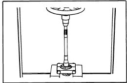
FIG. 5 REMOVING PINION
GEAR BEARING INNER
RACE
2) Hold pinion flange stationary and remove pinion nut, then using suitable puller, remove pinion flange. Press drive pinion from carrier and remove rear bearing inner race, bearing spacer and adjusting washers. Remove oil seal. Remove pilot bearing together with pilot bearing spacer and front bearing inner race. Press rear bearing inner race from drive pinion. Using a drift, remove front and rear bearing outer races.
3) To disassemble differential case, use suitable puller and remove side bearings. NOTE - Keep left and right side bearings separate, they are not interchangeable. Remove ring gear by unfolding lock strap and loosening bolts. Punch off pinion shaft lock pin from ring gear side, then remove pinion shaft, pinion gears, side gears and thrust washers. NOTE - Mark gears and thrust washers for instaallation in their original position. Thoroughly clean and inspect all parts for wear or damage and repair or replace as necessary.
REASSEMBLY AND ADJUSTMENT

FIG. 7 MEASURING SIDE BEARING WIDTH
FIG. 6 MEASURING SIDE GEAR
CLEARANCE
Differential Case Assembly - 1) Assemble pinion gears, side gears and thrust washers in original position in differential case. Fit pinion shaft to differential case so that it aligns with lock pin holes. Adjust side gear-to-pinion gear backlash or adjust clearance between rear face of side gear and thrust washer. Install pinion shaft lock pin and lock in place with punch.
2) Apply gear oil to gear tooth surface and thrust surfaces and ensure gears rotate smoothly. Install ring gears on differential case and install bolts and new lock washers. NOTE -Tighten ring gear bolts diagonally while tapping around bolt heads with a hammer.
MEASURING DRIVE SHAFT PLAY
3) When replacing side bearings, measure bearing width with a .787" (20 mm) gauge and 5.5 lb (2.5 kg) weight block. Bearing width should be slightly smaller than gauge. Press fit side bearing inner race on differential case and side bearing outer race into side retainers. Install new oil seal on side retainer and apply grease to cavity between seal lips.
Drive Pinion Preload - 1) NOTE - Perform adjustment without pinion shaft oil seal installed. Press fit and rear bearing outer races into gear carrier. Insert suitable dummy shaft spacer (ST31851000), pinion height adjusting spacer and rear bearing inner race into suitable dummy shaft (ST31212000).
2) Fit drive pinion bearing spacer, washer, front bearing inner race, suitable dummy shaft collar (ST31214000) and pinion flange on dummy shaft and tighten drive pinion nut to specified torque.
ADJUSTING DRIVE PINION PRELOAD
3) Measure pinion bearing preload using suitable preload gauge (ST31275000) and select washer and spacer that will provide specified preload. NOTE - Preload of old bearing is the same as that of a new bearing. Pinion bearing adjusting washers are available in thicknesses of .0906-.1024" (2.3-2.6 mm). Pinion bearing adjusting spacers are available in lengths at 2.2126-2.22520" (56.2-57.2 mm) on 610 models and 2.0551-2.0945" (52.2-53.2 mm) on all other models.

DRIVE PINION HEIGHT - 1) Install suitable height gauge (ST3121000) on gear carrier with dummy shaft mounted. Measure clearance between tip end of height gauge and end surface of dummy shaft. Thickness of drive pinion height adjusting washer can be obtained by the following formula.
MEASURING DRIVE PINION HEIGHT
T=W + N - (H - D' - S) x.01 - .2
NOTE - Formula values are give in Millimeters
T = Thickness of adjusting washer needed.
W = Thickness of washer temporarily installed.
N = Clearance between gauge and dummy shaft.
D' = Figure marked on dummy shaft
S = Figure marked on height gauge
NOTE - If values signifying H, D, and S are not given, regard them as zero.
2) Fit correct pinion adjusting washer in drive pinion and press fit rear bearing inner race. Lubricate pinion front and rear bearings, then install drive pinion in carrier along with drive pinion bearing spacer and washer, front bearing race, front bearing pilot spacer, pilot bearing and oil seal. Install pinion flange and tighten pinion nut to specifications
Side Bearing Preload - 1) Required thickness of left and right side retainer shims can be obtained by the following formulas
SIDE BEARING PRELOAD FORMULA VALUES
T1 = (A + C + G1 - D) X .01 + .76 - E
T2 = (B + D+ G2) X .01 + .76 - F
NOTE  - Formula values are given in millimeters
T1 = Required thickness of left side retainer shim.
T2 = Required thickness of right side retainer shim.
A & B = Figure marked on gear carrier.
C & D = Figure marked on differential case. 
E & F = Difference in width of left or right bearing.
G1 and G2 = Figure marked on left or right retainers.
NOTE - If values signifying A,B,C,D,G1 and G2 are not given, regard them as zero.
2) Install differential case assembly in gear carrier in reverse order of disassembly. Fit correct shims and "O" ring seal in both side retainers and install retainers in carrier with arrow pointing as shown in illustration.
SIDE BEARING PRELOAD IDENTIFICATION MARKS

INSTALLING SIDE RETAINER
3) Using dial indicator, remove ring gear-to-drive pinion backlash and adjust if necessary. Check side bearing preload, and adjust if necessary by adding or removing side retainer shims. NOTE - If side bearing preload is readjusted, ring gear-to-drive pinion backlash must be checked and adjusted. If necessary
Final Inspection and Assembly - After all adjustments are to specifications, make tooth contact pattern test and make any necessary correction. See Gear Tooth Contact Pattern of beginning of this section. Install rear cover and tighten nuts to specifications. Refill axle assembly to correct level with gear oil.
MEASURING RING GEAR BACKLASH


Friday, March 23, 2012

0 Arrow/Colt 1976-77 Drive Axles Repair Manual

DESCRIPTION
Rear axle is of the banjo type, utilizing the removable carrier style differential. Light weight construction joins split tubular housings for each side with center covers welded to axle housing. Final drive is of the hypoid style. Axle shafts are semi-floating type supported with bearings at their respective ends in axle housing. Bearings are fitted to axles with pressure type bearing retainers. Pinion bearing preload side bearing preload, and pinion depth adjustment are made with shims while differential side gears are adjusted with spacers

REMOVAL AND INSTALLATION
Axle Shafts and Bearings
FIG. 1 MEASURING AXLE SHAFT DEFLECTION
Removal - 1) Raise and suitable support rear axle housing so rear wheels clear ground. Remove rear wheel and brake back plate nuts, then disconnect wheel cylinder brake line. Fix suitable puller set (CT-1003 & C-637) to lug studs and work side hammer until axle shaft is free to be withdrawn. Set brake back plate with parking brake attached out-of-way. Using suitable tool (C-637 with hook) remove axle shaft oil seal.
2) To remove axle bearing proceed as follows: Grind down bearing retainer at one point until retainer thickness is .04-.06" (1.0-1.5 mm), then chisel ground portion and remove retainer. Using suitable bearing puller or press (CT-1120) remove bearing from axle.
3) Using a dial indicator, inspect axle shaft deflection in three spots (see illustration). Replace axle shaft if specifications are exceeded.
4) Rear axle bearing should be replaced when bearing noise is detected, when bearing axial free play exceeds .014-.016" (.36-.41 mm) or if bearing radial free play exceeds .001-.002" (.03-.04 mm) at approximately 11 lbs. (5.0 kg) measuring force.
5) Inspect wheel hub bolts for tightness and bearing outer retainer for deformation ,replace defective parts as nessary.

Installation - 1) Fit outer bearing retainer flat side against shaft splined end, then install bearing and inner bearing retainer. Seat bearing retainer with smaller chamfered side directed to the bearing. NOTE -Ensure bearing is completely seated.
FIG. 2 EXPLODED VIEW OF AXLE SHAFT ASSEMBLY
2) Lightly coat lips of oil seal and using suitable oil seal installer (DT-1007B & CT-1008) fit axle shaft oil seal in rear axle housing.
3) Using packings and shims in proper sequence, set clearance between bearing and outer bearing retainer to .00-.01" (.0-.25 mm).
4) Carefully insert axle shaft assembly into axle housing using care not to damage seal. Slightly turn shaft until splines line up with differential side gears. Align packing oil holes with outer bearing retainer and tighten bearing retainer to axle housing flange. Connect brake line to wheel cylinder and bleed air from system.

DIFFERENTIAL CARRIER
FIG. 3 REMOVING DIFFERENTIAL
GEAR HOUSING
Removal - Drain oil from rear axle differential housing, then disconnect propeller shaft. Pull out both rear axle shafts approximately 2 1/3". Remove differential gear housing mounting nuts and withdraw the differential gear carrier. It may be necessary to top outside of housing to break gear carrier loose.
Installation - Lightly coat each bearing and gear with oil. Apply sealing compound on packing and axle housing seat, then assemble gear carrier to housing with nuts and tighten. Fill differential gear housing with .96 quart of suitable multi-purpose gear oil (API GL-5).

OVERHAUL
Disassembly
FIG. 4 REMOVING DIFFERENTIAL
SIDE BEARINGS
Differential Gear Assembly - 1) Remove bearing carrier cap and lever gear case assembly from housing. Using suitable bearing puller tool (C-293-P & C293-39) pull differential side bearing. Keep right and left bearings and shims in sequence for reassembly
2) Remove ring gear lock plate tabs and loosen bolts in diagonal sequence, then remove ring gear. Drive out pinion shaft lock pin from ring gear back side using a punch, pull out pinion shaft and pinion. Pinion side gears and spacers are now accessible. Note placement of side gear and spacers and ensure they are reassembled in same position.

Drive Pinion Disassembly - 1) Hold end yoke with suitable tool (C-3281) and remove lock nut, then remove end yoke. Using a wheel puller, force out drive pinion with adjusting shim, rear inner bearing race, spacer and preload adjusting shim.
FIG. 6 REMOVING DRIVE
PINION FRONT BEARING
OUTER RACE
2) With suitable bearing puller (C-293-P & C-293-39) remove rear bearing inner race and at same time, pull of dive pinion adjusting shim. Using suitable drift, remove front drive pinion bearing outer race and oil seal. Repeat some procedure to remove bearing outer race.

INSPECTION
Check differential gears for correct tooth contact and replace gears if wear is excessive. Inspect bearing faces for roughness or score marks and replace, if necessary, bearing assembly. Ensure splines of side gears and rear axle shafts fit correctly. Check clearance between pinion gears and pinion shaft, if wear is excessive, replace components.
NOTE - To check gear tooth contact using pain impression method, refer to beginning of this section.

FIG. 7 EXPLODED VIEW OF COLT SEPARATE HOUSING REAR AXLE ASSEMBLY


REASSEMBLY AND AJDUSTMENT
FIG. 8 CHECKING DIFFERENTIAL PINION
AND SIDE GEAR BACKLASH
Case Assembly - 1) Install thrust washers (spacers) behind side gears in their original position and assemble pinion and side gears in differential. Insert both pinion gears with pinion washers attached, so they mesh with side gears. It may be necessary to slightly rotate pinions to achieve desired meshing. Insert drive pinion shaft.
2) Check pinion and side gear backlash as shown in illustration. If backlash is beyond 0-.003" (0-.08mm) adjust by selecting a side gear thrust washer (spacer) of correct size. If backlash is to be adjusted, ensure right and left sides are equally shimmed.
3) Thoroughly clean all dirt from ring gear mounting surface of differential case. Install bolts and lock washers. Tighten bolts alternately in a diagonal sequence and bend over lock tabs. Ensure lock washers are in contact with case rib after final torque is performed.
Drive Pinion - Using a suitable drift and hammer or a press, seat front and rear bearing outer races into gear carrier ensuring that outer races do not cock. Ensure bearing races are completely seated before proceeding. Install shim between drive pinion and rear bearing. Using suitable bearing installer (CT-1075) press bearing onto drive pinion shaft. If drive pinion and bearings are scheduled to be reused, shims should be replaced with new ones of same thickness. In instances where the gear set is to be replaced, install new shims that are the same thickness as the used shims on drive pinion NOTE - When determining the desired thickness of shim pack, amount of compression the desired thickness of shim pack, amount of compression (sinkage) of shim pack and wear of the beating (where old bearing is reused) must be taken into consideration.
Drive Pinion Depth - Install drive pinion spacer, front bearing, washer, end yoke and washer in order of removal. Fit pinion shaft retaining nut and slowly tighten nut, continously checking, until pinion bearing preload is 6-9 INCH lbs (7-10 cmkg) with oil seal not installed. Place suitable cylinder gauge on inside bearing pedestals of gear carrier housing. Place a block gauge on top end of drive pinion and slip a feeler gauge between the two gauges should be .0118" (.300 mm). This is the standard height and any deviation from this height will be marked on the head of the pinion shaft and side of ring gear. To calculate the correct pinion height, add or subtract the variation value from the standard height.
NOTE - Stamped values are in hundredth millimeters. Add or subtract the correct amount of shims an necessary.

Pinion Bearing Preload - The adjustment must be performed after the setting of the drive pinion depth. Remove end yoke and insert the bearing preload adjusting shim between pinion spacer and bearing, then tighten end yoke to 9-11 INCH lbs. (10-13 cmkg). In addition to the preload adjusting shims there are spacers available to provide proper adjustment. After finishing adjustment of drive pinion bearing preload remove the end yoke and apply a thin coat of grease to outer surface of oil seal, then drive seal into position in gear carrier. After greasing oil seal lip, insert end yoke and tighten nut.

Side Bearing Preload - Fit each side into differential case leaving shims out; use suitable tool (CT-1102) for this procedure. Ensure side bearings are completely seated before proceeding. Install differential case assembly on gear carrier, then calculate the clearance between side bearing outer race and gear carrier as shown in illustration. After obtaining clearance add .002" (.05 mm) preload figure to each side. Insert shims equally on both sides. Align gear carrier end bearing cap index marks, then tighten cap retaining bolts.


FIG. 9 MEASURING CLEARANCE
BETWEEN SIDE BEARING AND
GEAR CARRIER
Ring Gear Deflection - Attach a dial indicator to back side of ring gear and measure deflection. If ring gear has excessive deflection, correct position of the assembly in relation to differential case and again perform measurement. Replace ring gear or differential case as necessary.

Drive Pinion Depth - Measure backlash of drive pinion is at least four different spots on ring gear with drive pinion securely fixed in final position. Set up a dial indicator on ring gear teeth edges. If measured backlash is greater than .005-.007" (.13-.18 mm), shift shims from ring gear side to the back of the ring gear to obtain pro[er backlash. If the measure value is less than standard value, reverse the moving of shims as stated above. Side bearing shims are available in various thicknesses.
NOTE - Check gear tooth contact patter using point impression method described at beginning of this section.

Final Inspection and Assembly - Lightly coat each gear and bearing before and during reassembly with gear oil. After installing each component, ensure all rotating parts are free to move smoothly. Install differential gear assembly to axle housing after applying sealing agent and tighten gear carrier mounting nuts in diagonal sequence.


2012 BY ManualTransformerOnline Manual Sharing