Showing posts with label Mazda. Show all posts

Saturday, October 20, 2012

0 Mazda 121 1990 Workshop Manual

Repair and Factory Service Workshop Manual
Make: Mazda
Model: 121
Year: 1990


What's Inside:

  • General Information
  • Pre-Delivery Inspection and Scheduled Maintenance Service
  • Engine
  • Lubrication
  • Cooling System
  • Fuel and Emission Control System EGI-S
  • Engine Electrical System
  • Clutch
  • Manual Transaxle
  • Automatic Transaxle
  • Front and Rear Axles
  • Steering System
  • Braking System
  • Wheels and Tires
  • Suspension
  • Body
  • Body Electrical System
  • Heater and Air Conditioner Systems
  • Technical Data
  • Special Tools
  • Wiring Diagrams
File Size: 111 MB
File Type: PDF, RAR

Wednesday, August 22, 2012

0 Mazda 1975-77 Drive Axles Repair Guide

Models Covered:

  • GLC
  • Mizer
  • 808
  • RE Pickup
  • RX-3SP
  • RX-4
  • Cosmo
DESCRIPTION
Axle housing is banjo type with removable differential carrier and semi-floating axle shafts. Ring and pinion are hypoid type, in which centerline of pinion is set below centerline of ring gear. Differential case may be either two pinion or four pinion design. The axle shafts are retained in housing by ball bearing and bearing retainers at axle housing outer ends.
AXLE RATIO AND IDENTIFICATION
All Mazda models use one basic type of rear axle assembly. Any differences in Removal and Installation or Overhaul procedures will be noted where they occur. To determine axle ratio, divide number of ring gear teeth by number of pinion teeth.
REMOVAL AND INSTALLATION
Axle Shafts and Bearings
Removal (All Exc. Pickup) - Remove wheel and tire assembly and brake drum or disc. Remove brake shoes and return springs (drum brake models). Remove center cap adapter (if equipped). Remove brake backing plate and bearing retainer to axle housing. use slide hammer and adapter to remove axle shaft assembly from housing.
Bearing Replacement (All Exc. Pick-Up) - Remove axle bearing and collar using a press and a suitable bearing adapter (49 0259 745). NOTE - If pressure necessary to remove bearing exceeds 10 tons, or if bearing adapter is not available, grind bearing retaining collar down and cut with a chisel to remove. To reassemble, apply a light coat of oil to axle shaft and place bearing retainer and spacer on shaft. Position bearing on shaft with sealed side toward axle shaft flange, then press bearing on shaft until spacer contacts shaft shoulder. Next, press bearing retaining collar on shaft until it seats firmly against bearing. NOTE - Do not press bearing, and collar on shaft at the same time. In addition, if collar is installed with less than 3 tons pressure, replace with a new part.
Installation (All Exc. Pick-Up) - 1) Apply a light coat of grease to oil seal in axle housing. Check axle shaft end clearance as follows: Install backing plate and gasket temporarily and measure depth of bearing seat in axle housing. Then, measure width of axle bearing outer race. The difference between the two measurements indicates the required thickness of shim.
2) Shims are available in thicknesses of .004" (.1 mm) and .016" (.4 mm). After selecting correct shim pack, apply sealant to shims and position brake backing plate and shims on axle housing. Install axle shaft assembly in housing using a new gasket, then install and tighten retainer bolts. At this time, recheck end play; maximum end play allowable is .004" (.1 mm). Install brake shoes, return springs, brake drum, and wheel and tire assembly.
Removal (Pickup) - Remove wheel and tire assembly, then remove brake drum and brake shoes. Remove parking brake cable retainer and disconnect brake lines at wheel cylinders. Remove nuts attaching backing plate and bearing housing to axle housing, then pull axle shaft, backing plate, bearing housing assembly, and shims off axle housing.
Bearing Replacement (Pickup) - Straighten tabs of lock washer, and using suitable spanner wrench (49 0603 622A), remove lock nut and lock washer. Using a puller, withdraw bearing and housing assembly from axle shaft, then remove backing plate. Remove bearing and oil seal from housing. To reassemble, reverse disassembly procedure.
Fig. 1 Axle Shaft Assembly (Except Pickup)
Fig. 2 Axle Shaft Assembly (Pickup)


Installation (Pickup) - 1) Install axle shaft, backing plate, and bearing housing to rear axle housing, temporarily attaching with two bolts and nuts. Mount dial indicator on backing plate and check axle shaft end play. End play should be .002-.006" (.05.-.15 mm).
2) NOTE - If both axle shafts were removed, a special procedure must be followed: The end play for this first axle shaft installed should be set to .026-.033" (.65-.85 mm). The second axle shaft installed should be set to the normal end play of .002-.006" (.05.-15mm).
3) After installing correct shim pack, install and tighten oil attaching bolts and nuts. Install brake shoes and drum. Connect fluid lines to wheel cylinders, adjust brakes, and bleed system. Install and tire assembly.
DIFFERENTIAL CARRIER
Remove & Installation - Raise vehicle until rear wheels are clear of ground. Remove drain plug and drain rear axle lubricant, reinstall plug and tighten. Remove axle shafts. Mark propeller shaft and pinion flange for reassembly reference, then disconnect propeller shaft.Remove carrier attaching nuts and withdraw carrier from axle housing. To install, reverse removal procedure, making sure to refill axle with lubricant.
OVERHAUL
Disassembly
1) Mount carrier in a suitable repair stand. Attaching a dial indicator to carrier (with button of indicator contacting back face of ring gear) and check ring gear deflection. Maximum allowable deflection is .004" (.1 mm); replace ring and pinion if above specification. Punch identification marks on side bearing supports of carrier, differential bearing caps, and side bearing adjuster. Remove adjuster lock plates, loosen bearing cap attaching nuts or bolts, and slightly back off adjusters to relieve preload.
Fig. 3 Measuring Drive Pinion Installed Height
2) Remove bearing caps and adjusters, then withdraw differential assembly from carrier, making sure side bearing races remain with their respective bearings. If necessary for replacement, use a suitable puller and remove side bearings from gear case. Straighten lock tabs, remove ring gear attaching bolts, and separate ring gear from gear case.
3) On all models except RX-4 and Cosmo, drive out differential pinion shaft lock pin with a punch and remove pinion shaft. Rotate pinion gears 90 degrees and remove gears, thrust washer, thrust block (if equipped), and differential side gears. On RX-4 and Cosmo models, remove bolts joining differential case halves and separate case. Remove side gears, thrust washers, pinion gears, and spider.
4) On all models, remove pinion nut and pinion flange. Remove drive pinion and rear bearing assembly, adjusting shims (if equipped), spacer, and bearing collar (if used). NOTE - It may be necessary to tap end of pinion with a soft hammer to remove from carrier. Remove front oil seal and with draw from pinion bearing. Using a press, remove rear bearing from drive pinion, then lift off pinion adjusting shim. If necessary for replacement, use a drift punch and remove pinion bearing races from carrier.
REASSEMBLY AND ADJUSTMENT
Drive Pinion Depth - 1) NOTE - The use of a suitable dial indicator assembly (49 0727 570) and pinion gauging set (49 0305 555), all except B1600; or (49 0603 55A, B1600) is required for this procedure. Install dial indicator on gauge body, place gauge body on a surface plate and preload indicator .04"-.12" (1-3 mm). When preloaded, turn outer ring of indicator assembly to "zero" gauge.
2) Make sure differential bearing bores are free of dirt and burn, then install drive pinion, dummy bearing, and original pinion depth shim into carrier. Place gauge block on pinion and position indicator assembly on black so button of indicator contacts lowest portion of differential bearing bore.
3) Record the amount indicator moves in a "+" (plus) or, "-" (minus) direction from zero. Remove gauging assembly and pinion from carrier. Check rear face of pinion for the machining correction figure. If pinion is marked "+" (plus), SUBTRACT amount specified on pinion from dial indicator reading; if marked "-" (minus). ADD amount to indicator reading NOTE - Figures on pinion are hundredth millimeters.
4) Place dummy bearing and rear pinion bearing on surface plate and compare heights. If pinion bearing is higher than dummy bearing. SUBTRACT difference from dial indicator reading; if pinion bearing is lower than dummy bearing. ADD amount to indicator reading.
5) Select correct pinion depth adjusting shim to be used for reassembly by adding or subtracting the amount determined in steps 2), 3), and 4) from the thickness of the original pinion depth shim used during gauging process. Position correct shim on pinion and install pinion bearing.
Fig. 4 Exploded View of Mazda Rear Axle Assembly Showing Both Two and Four  Pinion Type Differential
                          Pinion Depth Adjusting Shims
                   (All Models Except RX-4 & Cosmo)
Identification Mark                                    Thickness In. (mm)
08..............................................................  .121 (3.08)
11..............................................................  .122 (3.11)
14..............................................................  .124 (3.14)
17..............................................................  .125 (3.17)
20..............................................................  .126 (3.20)
23..............................................................  .127 (3.23)
26..............................................................  .128 (3.26)
29..............................................................  .130 (3.29)
32..............................................................  .131 (3.32)
35..............................................................  .132 (3.35)
38..............................................................  .133 (3.38)
41..............................................................  .134 (3.41)
44..............................................................  .135 (3.44)
47..............................................................  .137 (3.47)
52..............................................................  .139 (3.52)
55..............................................................  .140 (3.55)
58..............................................................  .141 (3.58)
61..............................................................  .142 (3.61)
64..............................................................  .143 (3.64)
67..............................................................  .145 (3.67)
70..............................................................  .146 (3.70)
73..............................................................  .147 (3.73)
Pinion Bearing Preload (W/ Solid Bearing Spacer) - 1) Position drive pinion and rear bearing assembly into carrier, then install bearing spacer and preload shims onto pinion. Install front pinion bearing and pinion flange (do not install oil seal at this time). Install pinion nut and tighten to 110 ft. lbs. (15 mkg) on 1200 models, or 130 ft. lbs.  (18 mkg) on R-100 models.
Fig. 5 Installing Drive Pinion Bearing
Collapsible Spacer
Pinion Bearing Preload (W/ Collapsible Bearing Spacer) - 1) Position drive pinion in carrier and install bearing spacer. Place front pinion bearing in position on pinion gear, hold gear fully forward, and drive bearing over pinion until seated. Apply grease to lip of pinion oil seal and install seal into carrier. Install flange on pinion by tapping with a soft hammer. Install pinion washer and nut. Before tightening nut (when pinion preload is zero), check oil seal drag using a torque wrench. Tighten pinion nut as follows:
Application                                      Ft. Lbs. (mkg)
GLC, Mizer, 808, RX-35P............. 94 (13)
RX-4 & Cosmo...................... 101(14)
RE Pickup...................................... 145(20)
2) With nut tightened, check preload using a torque wrench mounted on pinion nut. If preload is not specified (see Axle Assembly Specifications), continue tightening nut and checking preload until specified preload is obtained. CAUTION - Preload builds quickly. Nut should be tightened a little at a time and preload checked after each slight amound of tightening.
Case Assembly - 1) On all models except RX-4 and Cosmo, install a thrust washer on each differential side gear and install into case. Through openings in gear case, insert pinion gears exactly 180 degrees opposite each other. Rotate pinion gears 90 degrees so holes in gears line up with pinion shaft holes in gear case. Insert pinion shaft through case and pinion gears.
Fig. 6 Installing Pinion Shaft and Lock Pin
2) On RX-4 and Cosmo models, install a thrust washer on each differential side gear and install into case halves. Position pinion gears on spider and install spider into differential case half. Align identification marks, mate case halves, and install and tighten retaining bolts.
3) On all models, check backlash between side gears and pinion gears. Backlash should be less than .004" (.1 mm) ; if not, install selective thrust washers to bring backlash within specifications. Washers are available in thicknesses of .063" (1.6 mm), .067" (1.7 mm), .071" (1.8 mm), .079" (2.0 mm), .083" (2.1 mm), and .087" (2.2 mm). NOTE - Always use same thickness thrust washer for both side gears.
Fig. 7 Installing Differential Assembly in Housing
4) If equipped with thrust block, remove pinion shaft, install thrust block, and reinstall pinion shaft. On all models except RX-4 and Cosmo, drive lock pin into case to secure pinion shaft. Using a punch, stake lock pin hole to prevent pin from working loose. On all models, mount ring gear on case, then install and tighten ring gear attaching bolts. If removed, install differential side bearings.
Backlash and Side Bearing Preload - 1) Place differential case assembly into carrier making sure timing marks on ring and pinion gears are aligned. Install bearing adjusters and bearing caps, then tihgten bearing cap nuts or bolts finger tight. Turn adjuster with suitable spanner wrench (49 0259 720) until bearing end play is eliminated and some backlash exists between ring gear and pinion. Slightly tighten one bearing cap nut or bolt on each side of carrier.
Fig. 8  Adjusting Differential Bearing
Preload (Case Spread)
2) Mount a dial indicator to carrier flange so button of indicator contact one of the ring gear teeth at a right angle, then check backlash between ring and pinion gears. Using the spanner wrench, turn both bearing adjusters equally until backlash is as specified in Axle Assembly Specifications.
3) Differential bearing preload (case spread) is obtained by tightening bolt bearing adjusters equally. Tighten adjusters until the distance between pilot section of side bearing caps as specified in Axle Assembly Specifications. Tighten bearing cap nuts or bolts, then recheck backlash adjustment. Make a gear tooth pattern check to insure correct assembly, then install adjuster lock plates on bearing caps.


Wednesday, May 2, 2012

0 Mazda 1968-74 Models Drive Axles Repair Manual

MODELS COVERED:

  • 616 (1971)
  • 618 (1972-73)
  • 808 (1972-74)
  • 1200 (1971-72)
  • B1600 (1972-74)
  • R100 (1971-72)
  • RX-2 (1971-74)
  • RX-3 (1972-74)
  • RX-4 (1974)
  • RE (Rotary Pick-Up) (1974)
DESCRIPTION
Axle housing is banjo type with removable differential carrier and semi-floating axle shafts. Ring and pinion are hypoid type in which centerline of pinion is set below centerline of ring gear. Differential case may be either two pinion or four pinion design. The axle shafts are retained in housing by ball bearings and bearing retainers at axle housing outer ends.
AXLE RATIO AND IDENTIFICATION
All Mazda models use one basic type of rear axle assembly. Any differences in Removal and Installation or Overhaul procedures will be noted where they occur. To determine axle ratio, divide number of ring gear teeth by number of pinion teeth.
REMOVAL AND INSTALLATION
Axle Shaft and Bearings
Removal (All. Exc. Pick-Up) - Remove wheel and tire assembly and brake drum. Remove brake shoe return springs and brake shoes. On RX-4 models, remove center cap adapter from axle shaft flange. On all models, withdraw nuts attaching retainer and backing plate to axle housing, then use a suitable puller (49 0259 631 and 49 0223 630A) to remove axle from housing.
Bearing Replacement (All Exc. Pick-Up) - Remove axle bearing and collar using a press and a suitable bearing adapter (49 0259 745). NOTE - If pressure necessary to remove bearing exceeds 10 tons, or if bearing adapter is not available, grind bearing retaining collar down and cut with a chisel to remove. To reassemble, apply a light coat of oil to axle shaft and place bearing retainer and spacer on shaft. Position bearing on shaft with sealed side toward axle shaft flange, then press bearing on shaft until spacer contacts shaft shoulder. Next, press bearing retaining collar on shaft until it seats firmly against bearing. NOTE - Do not press bearing and collar on shaft at the same time. In addition, if collar is installed with less than 3 tons of pressure, replace a new part.

AXLE SHAFT ASSEMBLY (EXCEPT PICK-UP)
Installation (All Exc. Pick-Up - 1) Apply a light coat of grease to oil seal in axle housing. Check axle shaft end clearance as follows. Install backing plate and gasket temporarily and measure depth of bearing seat in axle housing. Then measure width of axle bearing outer race. The difference between the two measurements indicates the required thickness of shim.
2) Shims are available in thicknesses of .004" (.1 mm) and .016" (.4 mm). After selecting correct shim pack, apply sealant to shims and position brake backing plate and shims on axle housing. Install axle shaft assembly in housing using a new gasket, then install and tighten retainer bolts. At this time, recheck end play, maximum end play allowable is .004" (.1 mm). Install brake shoes, return springs, brake drum and wheel and tire assembly.
AXLE SHAFT ASSEMBLY (B1600 & RE PICK-UP)
Removal (B1600 and Pick-Up) - Remove wheel and tire assembly, then remove brake drum and brake shoes. Remove parking brake cable retainer and disconnect brake lines at wheel cylinders. Remove nuts attaching backing plate and bearing housing to axle housing, then pull axle shaft, backing plate, bearing housing assembly, and shims off axle housng.
Bearing Replacement (B1600 and RE Pick-Up) - Straighten tools of lock washer, and using a suitable spanner wrench (49 0603 621A), remove lock nut and lock washer. Using a puller withdraw bearing and housing assembly from axle shaft, then remove backing plate. Remove bearing and oil seal from housing. To reassemble, reverse disassembly procedure.
Installation (B1600 and RE Pick-Up) 1) Install axle shaft, backing plate, and bearing housing to rear axle housing, temporarily attaching with two bolts and nuts. Mount a dial indicator on backing plate and check axle shaft end play. End play should be .002-.006" (.05-.15 mm).
2) NOTE - If both axle shafts were removed, a special procedure must be followed: The end play for the first axle shaft installed should be set to .026-.033" (.65-.85 mm). The second axle shaft installed should be set to the normal end play of .002-.006" (.05-.15 mm).

DIFFERENTIAL CARRIER
Removal and Installation - Raise vehicle until rear wheels are clear of ground. Remove drain plug and drain rear axle lubricant, reinstall plug and tighten. Remove axle shafts. Mark propeller shaft and pinion flange for reassembly reference, then disconnect propeller shaft. Remove carrier attaching nuts and withdraw carrier from axle housing. To install, reverse removal procedure, making sure to refill axle with lubricant.

OVERHAUL
Disassembly 
MEASURING PINION HEIGHT
1) Mount carrier in a suitable repair stand. Attach a dial indicator to carrier (with button of indicator contacting backface of ring gear) and check ring gear deflection. Maximum allowable deflection is .004" (.1 mm); replace ring and pinion if above specification. Punch identification marks on side bearing supports of carrier, differential bearing caps, and side bearing adjusters. Remove adjuster lock plates, loosen bearing cap attaching nuts or bolts, and slightly back off adjusters to relieve preload.
2) Remove bearing caps and adjusters, then withdraw differential assembly from carrier, making sure side bearing races remain with their respective bearings. If necessary for replacement, use a suitable puller and remove side bearings from gear case. Straighten lock tabs, remove ring gear attaching bolts, and separate ring gear from gear case.
3) On all models except RX-4, drive out differential pinion shaft lock pin with a punch and remove pinion shaft. Rotate pinion gears 90 degrees and remove gears, thrust washers, thrust block (if equipped), and differential side gears. On RX-4 models, remove bolts joining differential case halves and separate case. Remove side gears, thrust washers, pinion gears, and spider.
4) On all models, remove pinion nut and pinion flange. Remove drive pinion and rear bearing assembly, adjusting shims (if equipped), spacer and bearing collar if used). NOTE - It may be necessary to top end of pinion with soft hammer to remove from carrier. Remove front oil seal and withdraw front pinion bearing. Using a press, remove rear bearing from drive pinion, then lift off pinion adjusting shim. If necessary for replacement, use a drift punch and remove pinion bearing races from carrier.
MAZDA REAR AXLE ASSEMBLY

REASSEMBLY AND ADJUSTMENT
Drive Pinion Depth - 1) NOTE -The use of a suitable dial indicator assembly (49 0727 570) and pinion gauging set (49 0305 555, all exc. pick-up; or 49 0603 555A, B1600 and RE pick-up) is required for this procedure. Install dial indicator on gauge body, place gauge body on a surface plate, and preload indicator .040-.120" (1-3 mm). When preloaded, turn outer ring of indicator assembly to "zero" gauge.
2) Make sure differential bearing bores are free of dirt and burrs, then install drive pinion, dummy bearing, and original pinion depth shim into carrier. Place gauge block on pinion and position indicator assembly on block so button of indicator contacts lowest portion of differential bore.
3) Record the amount indicator moves in a "+" (plus) or "-" (minus) direction from zero. Remove gauging assembly and pinion from carrier. Check rear face of pinion for the machining correction figure. If pinion is marked "+" (plus), SUBTRACT amount specified on pinion from dial indicator reading; if marked "-" (minus), ADD amount to indicator reading. NOTE - Figures on pinion are hundredth millimeters.
4) Place dummy pinion and rear pinion bearing on surface plate and compare heights. If pinion bearings is higher than dummy bearing, SUBTRACT difference from dial indicator reading, if pinion bearing is lower than dummy bearing, ADD amount to indicator reading.
5) Select correct pinion depth adjusting shim to be used for reassembly by adding or subtracting the amount determined in steps 2), 3), and 4) from the thickness of the original pinion depth shim used during gauging process. Position correct shim on pinion and install pinion bearing. Shims are available in the following thicknesses for all models except RX-4:
Identification Mark                              Thickness In. (mm)
08.......................................................   .121 (3.08)
11.......................................................   .122 (3.11)
14.......................................................   .124 (3.14)
17.......................................................   .125 (3.17)
20.......................................................   .126 (3.20)
23.......................................................   .127 (3.23)
26.......................................................   .128 (3.26)
29.......................................................   .130 (3.29)
32.......................................................   .131 (3.32)
35.......................................................   .132 (3.35)
38.......................................................   .133 (3.38)
41.......................................................   .134 (3.41)
44.......................................................   .135 (3.44)
SOLID BEARING PRELOAD SPACER
AND SHIMS
47.......................................................   .137 (3.47)
For RX-4 models, the following thickness shims are available
Identification Mark                             Thickness In. (mm)
52.......................................................   .139 (3.52)
55.......................................................   .140 (3.55)
58.......................................................   .141 (3.58)
61.......................................................   .142 (3.61)
64.......................................................   .143 (3.64)
67.......................................................   .145 (3.67)
70.......................................................   .146 (3.70)
73.......................................................   .147 (3.73)
Pinion Bearing Preload (W/ Solid Bearing Spacer) - 1) Position drive pinion and rear bearing assembly into carrier, then install bearing spacer and preload shims onto pinion. Install front pinion bearing and pinion flange (do not install oil seal at this time). Install pinion nut and tighten to 110 ft. lbs. (15 mkg) on 1200 models or 130 ft. lbs. (18 mkg) on R-100 models.
2) Using a torque wrench installed on pinion nut, measure turning torque of drive pinion through at least one full revolution. If preload is greater than specified (see Axle Assembly Specifications), a thicker shim or longer bearing spacer is required; if preload is less than specified, a thinner shim or shorter bearing spacer is required. Shims and spacer are available in the following thicknesses and lengths:
Identification Mark                               Thickness/Length In. (mm)
INSTALLING COLLAPSIBLE
BEARING SPACER
Shims
   4.....................................................   .013 (.34)
   6.....................................................   .014 (.36)
   8.....................................................   .015 (.38)
Spacer (1200 Model Only)
   10...................................................   1.658 (41.10)
   18...................................................   1.661 (41.18)
   26...................................................   1.664 (41.26)
   34...................................................   1.668 (41.34)
Spacer (R-100 Model Only)
   60...................................................   2.149 (54.60)
   68...................................................   2.152 (54.68)
   76...................................................   2.155 (54.76)
   84...................................................   2.159 (54.84)
INSTALLING PINION SHAFT
& LOCK PIN
3) After obtaining correct preload shim pack, remove pinion flange, install pinion oil seal, and reinstall pinion oil seal, and reinstall pinion flange. Tighten pinion nut to specification.
Pinion Bearing Preload (W/Collapsible Bearing Spacer) - 1) Position drive pinion in carrier and install bearing spacer. Place front pinion bearing in position on pinion gear, hold gear fully forward, and drive bearing over pinion until seated. Apply grease to lip of pinion by tapping with a soft hammer. Install pinion washer and nut. Before tightening nut (when pinion preload is zero), check oil seal drag using a torque wrench. Tighten pinion nut as follows:
Application                                       Ft. Lbs. (mkg)
808 (W/1300 cc)...................................   87 (12)
INSTALLING DIFFERENTIAL
ASSEMBLY
RX-4....................................................  101(14)
B1600, RE (Rotary Pick-Up)...................  145(20)
All Others..............................................   94(13)
2) With nut tightened, check preload using a torque wrench mounted on pinion nut. If preload is not as specified (see Axle Assembly Specifications), continue tightening nut and checking preload until specified preload is obtained. CAUTION - Preload builds quickly. Nut should be tightened a little at a time and preload checked after each slight amount of tightening.
Case Assembly - 1) On all models except RX-4, install a thrust washer on each differential side gear and install into case. Through openings in gear case, insert pinion gears exactly 180 degrees opposite each other. Rotate pinion gears 90 degrees so holes in gears line up with pinion shaft holes in gear case. Insert pinion shaft through case and pinion gears.
ADJUSTING BEARING PRELOAD
(CASE SPREAD)
2) On RX-4 models, install a thrust washer on each differential side gear and install into case halves. Position pinion gears on spider and install spider into differential case half. Align identification marks, mate case halves, and install and tighten retaining bolts.
3) On all models, check backlash between side gears and pinion gears. Backlash should be less than .004" (.1 mm); if not, install selective thrust washers to bring backlash within specifications. Washers are available in thicknesses of .063" (1.6 mm), .067" (1.7 mm), .071" (1.8 mm), .079" (2.0 mm), .083" (2.1 mm), and .087" (2.2 mm). NOTE - Always use some thickness thrust washer for both side gears.
4) If equipped with thrust block, remove pinion shaft, install thrust block, and reinstall pinion shaft. On all models except RX-4, drive lock pin into case to secure pinion shaft. Using a punch, shake lock pin into case to secure pinion shaft. Using a punch, stake lock pin hole to prevent pin from working loose. On all models, mount ring gear on case, then install and tighten ring gear attaching bolts. If removed, instal differential side bearings.
Backlash & Side Bearing Preload - 1) Place differential case assembly into carrier making sure timing marks on ring and pinion gears are aligned. Install bearing adjusters and bearing caps, then tighten bearing cap nuts or bolts finger tight. Turn adjusters with a suitable spanner wrench (49 0259 720) until bearing end play is eliminated and some backlash exists between ring gear and pinion. Slightly tighten one bearing cap nut or bolt on each side carrier.
2) Mount a dial indicator to carrier flange so button of indicator contacts of the ring gear teeth at a right angle then check backlash between ring and pinion gears. Using the spanner wrench, turn both bearing adjusters equally until backlash is as specified in Axle Assembly Specifications.
3) Differential bearing preload (case spread) is obtained by tightening both bearing adjusters equally.  Tighten adjusters until the distance between pilot section of side bearing caps in as specified in Axle Assembly Specifications. Tighten bearing cap nuts or bolts, then recheck backlash adjustement. Make a gear tooth pattern check to insure correct assembly, then install adjuster lock plates on bearing caps.


Thursday, January 12, 2012

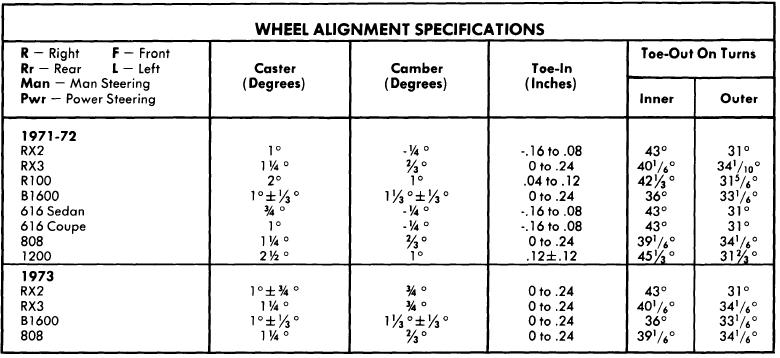
0 Mazda 1971-73 Wheel Alignment Repair Guide

1971-73 MAZDA SPECIFICATIONS AND ADJUSTMENTS

TIRE INFLATION (COLD)
Before attempting to check or adjust wheel alignment, ensure that tires are properly inflated.


CASTER
All Models Exc. B1600 - Caster is nonadjustable. If alignment is not within specifications, inspect for damaged parts and replace as necessary.

B1600 - To adjust, change shims between upper arm shaft and the support bracket or turn the upper arm shaft until specifications are obtained.

CAMBER
All Models Exc. B1600 - Camber is non adjustable. If alignment is not within specifications, inspect for damaged parts and replace as necessary.

B1600 - To adjust, change shims between upper arm shaft and the support bracket until specifications for camber are within limits.

TOE-IN
All Models - Position wheels to center position and loosen tie rod locking nuts at each end of tie rod. Check that tie rod ends are in the same position on each rod ensuring that the tie rods are the same length. Turn tie rods by equal amounts until the toe-in is within specifications. Tighten locking nuts.

0 Mazda 1974-76 Models Wheel Alignment Repair Guide

MAZDA SPECIFICATIONS AND ADJUSTMENTS

TIRE INFLATION (COLD)
Before attempting to check or adjust wheel alignment, make sure tires are properly inflated. Refer to manufacturer's specifications given in owner's manual.

CASTER
808, RX2 & RX3 MODELS - Caster is not adjustable. If caster angle is not to specifications, inspect suspension for wear or damage and repair or replace components as necessary.

RX4 - Caster and camber angles can be adjusted by changing position of the shock absorber support. To adjust remove four nuts attaching shock absorber support to fender apron. Raise front of vehicle and support with jack stands, then remove wheel on side to be adjusted. Press shock absorber downward and change position of support according to following table and illustration. Tighten shock absorber support attaching nuts. Install wheel, lower vehicle and recheck caster and camber angles.


Pickup - To adjust, change shims between upper arm shaft and support bracket or turn upper arm shaft until specifications are obtained.


CAMBER

808, RX2, and RX3 - Camber is not adjustable. If camber angle is not to specifications, inspect suspension for wear or damage and repair or replace components as necessary.

RX4 - See procedure given under Caster adjustment.

Pickup - To adjust, change shims between upper arm shaft and support bracket until specifications for camber are within limits.

TOE-IN
All Models - Position wheels to center position and loosen tie rod locking nuts at each end of tie rod. Check that tie rod ends are in the same position on each rod ensuring that the tie rods are the same length. Turn tie rods by equal amounts until the toe-in is within specifications. Tighten locking nuts.


Wednesday, November 23, 2011

0 1965 Import Vehicles Ball Joint Checking Guide

ARROW / COLT

All Models - With components removed from control arm and ball joint still installed, check following: Horizontal and vertical free play (0"), and ball joint rotation starting torque 4-6 ft. lbs. (6-8Nm). Replace ball joints if correct specifications are not obtained

AUDI

Fox - Clearance of ball joint with pressure applied by leverage should be .04-.10" (1.0-2.5 mm). if not replace ball joints

BMW

All Models - With lower control arm removed, measure axial (up and down) movement of ball joint stud. If movement exceeds .0945", replace ball joint.

COURIER

All Models - Check working surfaces of ball joints and studs for wear or damage. End play should not exceed .031" (.8 mm), if end play is excessive, replace ball joint.

DATSUN

All Models (Exc. 620 Pickup) - Remove lower control arm. Use appropriate spring tension gauge and and attach it to top of ball joint stud nut. Measure force (INCH Lbs.) required to move ball joint stud laterally. If measurement is not within specifications, replace ball joint


FIAT

All Models - With vehicle raised and supported under lower control arms, grasp wheel at top and bottom and try to shake wheel. If any movement is noted, control arm must be removed for further inspection.

HONDA

All Models - Raise and support front of vehicle. Attach dial indicator onto lower control arm with indicator tip on steering knuckle near ball joint. Place pry bar between lower control arm and steering knuckle. NOTE - Take care not to damage ball joint rubber boot. Push on pry bar and observe movement on dial indicator. If movement is in excess of .020" (.5 mm), ball joint must be replaced.

JAGUAR

All Models - Upper ball joint must be replaced if signs of wear or play are evident. The lower ball joint is adjustable with shims if axial play exceeds .004-.006" (.10-.15 mm). Shims must not be removed to take excessive wear in ball pin and socket. If parts are excessively worn, replacement is required.

LANCIA

All Models - if ball joint shows excessive amounts of wear (play) replace ball joints.

LUV

With vehicle raised and supported under lower control arms, grasp wheel at top and bottom. Try to move wheel and replace ball joint if movement exceeds .06" (1.52 mm).

MAZDA

All Models - Check ball joint dust seal for wear or damage and if necessary, replace seal. Ball joint end play must not exceed .039" (1 mm). If end play exceeds specifications, replace ball joint

MERCEDES-BENZ

There should be no lateral movement of ball joint. Vertical movement is adjusted by adding or removing washers.

OPEL

All Models - Raise and support front of vehicle. Inspect ball joint rubber boots for damage and replace as necessary. If lower ball joint axial play exceeds .008" (2 mm), ball joint must be replaced.

PEUGEOT

All Models - When moving ball pin some friction torque should be felt. If ball pin can be moved without resistance end play is shown, replace ball joint.

RENAULT

All Models - Inspect ball joints for wear or excessive play. Replace ball joints as necessary.

SAAB

All Models - if ball joint exhibits excessive play, it must be replaced as a complete unit.

SUBARU

All Models - Check ball joint for excessive play by pushing and pulling on ball joint stud. Allowable looseness is less than .012". If play exceeds this specification, ball joint must be replaced.

TOYOTA

Corona and Pickup - To check lower ball joint, jack up lower suspension arm and check for ball joint looseness by moving wheel vertically and horizontally. Movement limit in vertical direction should be less than .04" (1 mm) Corona and .20" (5.0 mm) Pickup. Movement limit in horizontal direction should be less than .08" (2 mm). Corona and .09" (2.3 mm) Pickup.
NOTE -  Ensure other suspension parts are tight before checking ball joints. To check upper ball joints. disconnect upper suspension arm from steering knuckle. Turn ball stud and check for excessive looseness or tightness. Replace ball joint if it is excessively loose or tight.

All Other Models - Check for excessive looseness, proper operation and damaged ball stud. Replace as necessary.

TRIUMPH

All Models - Inspect ball joints for excessive wear or play. Replace ball joint as necessary.

VOLKSWAGEN

Type 1 - Raise front of behicle and turn steering to one side. Place pry bar tool over nut or bolt head mounting steering knucle to strut. Compress ball joint spring and place vernier caliper over top of ball joint and over bottom stud. Note caliper reading, then release lever and record caliper travel. Increase reading is ball joint play. Replace ball joints as necessary

Type 2 - Raise front of vehicle and turn steering to one side. Insert pry bar tool VW 281a (or equivalent) under lower control arm and over top of strut mounting. Fit a vernier caliper on lower or upper torsion arm and steering knuckle. Record measurement. Press down with lever and measure travel of vernier caliper. IF travel exceeds specifications, replace ball joint.

All Other Models - Raise and support, then turn steering to one side. Install suitable levering tool so that ball joint spirng may be compressed. With spring compressed, position a vernier caliper with lower jaw on ball joint stud and upper jaw on top of clamping bolt for ball joint stud. Note reading. Slowly release tension from spring and not travel of caliper. This reading indicates ball joint play. If specified play is exceeded replace ball joint.

VOLVO

All Models - Maximum permitted axial play for lower ball joint is 12" (3 mm). Check ball joint by prying back and forth with a bar. If specifications are exceeded, replace ball joints.


Saturday, November 19, 2011

0 1975 Vehicles Ball Joint Checking

ALFA ROMEO
All Models - Check working surfaces of ball pins and their seats, and ball joint studs for damage or wear. Axial play should not exceed specifications (.04"). Replace complete ball joint unit when indicated

BMW
All Models - With lower control arm removed, measure axial (up and down) movement of ball joint stud. If movement exceeds .0945", replace ball joint.

COLT
All Models - With components removed from control arm and ball joint still installed, check the following: Horizontal and vertical free play (0") and ball joint rotation starting torque 4-7 ft. lbs. (.6-1.0 mkg). Replace ball joints if correct specifications are not obtained

COURIER
All Models - Check working surfaces of ball joints and studs for wear or damage. End play should not exceed .031" (.8mm). If end play is excessive, replace ball joint.

DATSUN
All Models (Exc. 620 Pickup) - Remove lower control arm. Measure axial movement by lifting and depressing ball joint stud. Difference between these two measurements is axial movement. Using suitable spring tension gauge attached to top of ball joint stud measure force (INCH lbs.) required to move ball joint stud laterally. If either measurement is not within specifications, replace ball joint.
Ball Joint Specifications
  Application                      Axial                     Lateral INCH Lbs. (cmkg)
B210..................   .004-.012"(.1-.3 mm)..........................  52 (60)
610,710 and 280Z....    .004" (.1 mm)..............................   35 (40)

FIAT
All Models - With vehicle raised and supported under lower control arms, grasp wheel at top and bottom and try to shake wheel. If any movement is noted, control arm must be removed for further inspection

HONDA
All Models - Raise and support front of vehicle. Attach dial indicator onto lower control arm with indicator tip on steering knuckle near ball joint. Place pry bar between lower control arm and steering knuckle.

JAGUAR
All Models - Upper ball joint must be replaced. If signs of wear or play are evident. The lower ball joint is adjustable with shims if axial play exceeds .004-.006" (.10-.15 mm). Shims must not be removed to take up excessive wear in ball pin and socket. If parts are excessively worn, replacement is required.

LUV
With vehicle raised and supported under lower control arms, grasp wheel at top and bottom. Try to shake wheel and if any movement is noted, inspect front suspension for wear or damage.

MAZDA
All Models - Check ball joint dust seal for wear or damage and, if necessary, replace seal. Ball joint end play must not exceed .039" (1 mm). If end play exceeds specifications, replace ball joint.

OPEL
All Models - Raise and support front of vehicle. Inspect ball joint rubber boots for damage and replace as necessary. Using suitable gauge (J-23745) measure axial play. If axial play is more than .080" (2 mm), ball joint must be replaced.

PEUGEOT
All Models - Inspect ball joints for roughness or excessive wear. Replace ball joints as necessary.

PORSCHE
All Models - When moving ball pin some friction torque should be felt. If ball pin can be moved without resistance and end play is shown, replace ball joint.

RENAULT
All Models - Inspect ball joints for wear or excessive play. Replace ball joint as necessary.

SAAB
All Models - If ball joint exhibits excessive play, it must be replaced as a complete unit.

SUBARU
All Models - Check ball joint for excessive play by pushing and pulling on ball joint stud. Allowance loosness is less than .012". If play exceeds this specification, ball joint must be replaced.


Wednesday, November 16, 2011

0 Wheel Bearing Adjustment Guide

ALFA ROMEO
All Models - While rotating hub, tighten spindle nut to 18 ft. lbs. Loosen nut, then retighten to 7 ft. lbs. Back off on nut 1/4 turn and install cotter key. If slot in spindle nut does not align with hole in spindle, tighten nut until it is possible to insert cotter key. After cotter key is installed, ensure that bearing retainer plate can be easily rotated by insterting a screwdriver in plate holes

AUDI
NOTE - The following procedure can only be performed using special tools indicated.

Model 100 (Front) - 1) Raise and support front of vehicle. Remove lower wheel bolt and replace with special wheel bolt adapter (V-104) and special dial indicator (G-43). By means of retaining screw on special tool (V1-104), adjust dial indicator to pretensioned position of 1 millimeter.

2) Grasp wheel at front and rear. First push inward on front while pulling outward on rear, record dial indicator reading. Reverse this procedure and record dial indicator reading. Difference between these two readings is wheel bearing play. If play exceeds .04-.07 mm, adjustment will be necessary.

3.) Remove cotter pin and castle nut. If there was too much play, tighten spindle nut until play is within specifications. If there was insufficient play, remove wheel, spindle nut and its shim. Replace and tighten spindle nut. Using 1 millimeter feeler gauge, loosen spindle nut until it is possible to insert feeler gauge between spindle nut and wheel hub. Attach special hub puller (V-26) and withdraw hub until it is firmly in contact with spindle nut. Remove puller and retighten spindle nut until it is within specifications

Model 100 (Rear) - Raise and support rear of vehicle. Remove grease cup and one wheel bolt. Attach special dial indicator (30-43), using wheel bolt adapter (40-104) and attachment (10-22). Dial indicator activator foot should be pretensioned to 1 millimeter against the stub axle. Grasp wheel at front and rear. Move wheel on horizontal axis. If reading on dial indicator is not .02-.04mm, adjustment will be necessary. Adjust by loosening or tightening spindle nut

NOTE - Fox front wheel bearing is not adjustable. Torque stub axle nut to 13 ft. lbs.

Fox (Rear) - Remove grease cup, cotter pin and castle nut. Tighten spindle nut and loosen for adjustment. Adjust by lightly tightening spindle nut until plain washer (beneath spindle nut) can just be moved from side to side, using screwdriver. Thin adjustment will correspond to .0012-.0027" (.03-06 mm) wheel bearing play.

AUSTIN
Austin Marina - Raise and support vehicle so that front wheel is not touching ground. Remove grease cup and attach suitable magnetic base dial indicator with base on brake drum and actuating foot touching spindle. Bearing wobble should be from .001-.005". If adjustment is required remove cotter pin and slacken castle nut. Torque castle nut to 5ft lb. while spinning wheel. Stop wheel, slacken castle nut, and retighten castle nut, finger tight only. Reinstall cotter pin. NOTE - At minimum end-float figure given a considerable amount of movement will  be felt in the front wheel. Do not reduce end-float below .001".

BMW
2002 Models - While rotating wheel hub, tighten castle nut to 22-24 ft. lbs., then rotate hub at least two more times. Loosen castle nut until bearing end play is noticed. Tighten castle nut to maximum of 2.2 ft. lbs., then loosen nut to nearest hole an install cotter key. NOTE - After adjustment, slotted washer should move easily, without noticeable resistance.

3.0 Si and 530 i Models - While rotating wheel hub, tighten castle nut to 7 ft. lbs. Loosen castle nut approximately 1/4 turn. Insert screwdriver in recess of bearing retainer washer and ensure washer can be rotated easily. Install suitable gauge holder (BMW 00 2 500) on wheel hub and install dial indicator with tip touching front axle stub. Move wheel hub back and forth several times and check bearing end play. Adjust castle nut until bearing end play is .0008-.0024". NOTE - Set bearing end play as close to lowest limit as possible. Install cotter key.

CAPRI
All Models - Rotate wheel, hub and drum assembly while turning adjusting nut to 17-25 ft. lbs. Back off nut one-half turn. Retighten adjusting nut to 10-15 INCH lbs. Reinstall cotter pin and check front wheel rotation

COLT
All Models - Tighten adjusting nut to 14.5 ft. lbs. After seating bearing components, loosen nut to 0 ft. lbs. Now make final adjustment to 3.6 ft. lbs. After installing lock cap, insert cotter pin. NOTE - Do not loosen adjusting nut more than 15 degrees to align spindle holes.

COURIER
All models - While rotating wheel, hub and drum assembly, tighten adjusting nut to 17-25 ft. lbs. Back adjusting nut off 1/2 turn and retighten nut to 6-8 ft. lbs. Install new cotter key and check wheel rotation.

DATSUN
All models - Tighten spindle nut to torque specifications in following table. Spin wheel and retorque spindle nut. Loosen nut according to specifications in following table and then tighten to align cotter key hole. Insert cotter pin.

Wheel Bearing Adjustment
Application                        Torque                  Loosen
B210..................................22-25....................90 Degrees
Pickup................................22-25....................40 to 70 Degrees
All Other.............................18-22...................60 Degrees

Model 124 and 131 - While rotating hub, torque spindle nut to 14.5 ft. lbs. Completely loosen nut and retighten to 5 ft. lbs. Loosen nut 30 Degrees and stake collar of spindle nut into machined slot on spindle. Attach dial indicator with magnetic base on brake drum and actuating foot on spindle. Hub end play should not exceed .004". NOTE - When ever spindle nut has been removed it must be replaced with a new nut.

FIAT (Cont.)
Models 128 and X 1/9 - Tighten front and rear spindle nuts to 112 ft. lbs. When spindle nuts are properly tightened, stake collar of spindle nut into machined slot on spindle.

HONDA
All Models (Front) - Front wheel bearings are not adjustable. Torque front spindle nut to 87-130 ft. lbs. (Civic CVCC)

JAGUAR
All Models - While rotating hub, tighten nut until no end play is evident. Loosen nut 1 or 2 flats to line up cotter key and install cotter key. End play should be measured with a dial indicator and should be .002-.006". If not within specifications, adjust axle nut to correct end play.

LUV
All Models - While rotating wheel, tighten spindle nut to 22 ft. lbs. Turn hub through two or three turns and loosen nut until just finger tight. Check free play. Using a pull scale attached to wheel stud, measure turning torque; adjust nut until pull recorded on scale is 1.1 to 1-2.6 lbs. when wheel begins to rotate.

MAZDA
All Models - With vehicle raised and supported under lower control arms, measure amount of bearing preload using a pull scale hooked on hub bolt. Preload should be 1.3-2.4 lbs. (81600) or .9-2.2 lbs. (all other models). If not to specifications, adjust by tightening spindle nut until correct bearing preload is obtained. Align slot of spindle nut with hole in spindle and install new cotter key.

MERCEDES-BENZ
All Models - While rotating hub, tighten clamping nut until hub can just be turned. Loosen clamping nut and release bearing tension by striking steering knuckle spindle with plastic hammer. Using a suitable dial indicator, check wheel bearing end play. End play should be .0004-.0008". Adjust clamping nut until end play is within limits. Tighten socket bolt of clamping nut. Washer between outer bearing and clamping nut should rotate with light pressure applied to it.

MG
Midget - Raise front of vehicle and remove each wheel. Remove caliper assembly, but do not disconnect hydraulic brake hose. Support caliper to prevent damage to hose. Attach suitable dial indicator and measure runout of hub at outer edge of brake rotor. If runout exceeds .006" remove rotor and reposition on hub. Torque spindle nut to 46 ft lbs. and recheck runout.

MGB and MGB/GT - Raise front of vehicle and remove fron wheels. Using suitable dial indicator, measure hub end play. Correct end play is .002-.004". If not within specifications, remove spindle nut, washer and outer bearing. Add or remove shims behind outer bearing, until correct end play is obtained with spindle nut torqued to 40-70 ft. lbs.

OPEL
All Models - Raise and support front of vehicle. While rotating wheel, torque spindle nut to 18 ft. lbs. Back off spindle nut 1/4 turn. If slot in spindle nut and hole in spindle do not align, back off nut until they are aligned and insert cotter pin. Properly adjusted wheel bearing will exhibit small amount of end play

PEUGEOT
All Models - While turning wheel tighten spindle nut to 22 ft. lbs. Loosen and retorque nut to 7 ft. lbs. Lock nut in this position by staking nut collar into slot of spindle.

PORSCHE
All Models - Turn wheel and tighten clamping nut just enough to seat roller bearings. Loosen until tab washer can be easily moved in a lateral direction (by means of screwdriver) and no perceptible bearing play is felt when hub is moved axially. Tighten screw on clamping nut to specified torque and recheck adjustment.

RENAULT
All Models (Front) - Front wheel bearings are not adjustable. Torque front spindle nut to 145 ft. lbs.

All Models (Rear) - Install washer and lock nut. Tighten lock nut to 36 ft. lbs. (5 mkg) to seat bearings. Loosen lock nut completely, then tighten nut to 1.4-2.9 ft. lbs. (.2-.4 mkg) and lock nut in place by bending flange into slot of lock nut.

SUBARU
All Models (Front) - Front wheel bearing is not adjustable. Tighten spindle nut to 174 ft. lbs.

4WD Station Wagon (Rear) - Rear wheel bearings are not adjustable. Tighten spindle lock nut to 145 - 181 ft. lbs.


Saturday, November 5, 2011

0 1974 Vehicles Ball Joint Checking

ALFA ROMEO
All Models - Check working surfaces of ball pins and their seats, and ball joint studs for damage or wear. Axial play should not exceed specifications (.04"). Replace complete ball joint unit when indicated.

BMW
All Models - With lower control arm removed, measure axial (up and down) movement of ball joint stud. If movement exceeds .0945", replace ball joint. See BMW in SUSPENSION Section.

CAPRI
All Models - To check ball joint wear, raise vehicle and attach a dial indicator to a suitable fixed pivot, with stem on ball joint cap. Raise wheel independently of vehicle and note maximum dial gauge reading. If gauge reading is in excess of .098", ball joint should be replaced.

COLT
All Models - With components removed from control arm and ball joint still installed, check the following: Horizontal and vertical free play (0"), and ball joint rotation starting torque 4-7 ft. lbs. (.6-1.0 mkg). Replace ball joints if correct specifications are not obtained.

DATSUN
All Models (Exc. 620 Pickup) - Remove lower control arm. See Datsun in SUSPENSION Section. Measure axial movement by lifting and depressing ball joint stud. Difference between these two measurements is axial movement. Using suitable spring tension gauge attached to top of ball joint stud, measure force (ft. lbs.) required to move ball joint stud laterally. If either measurement is not within specifications, replace ball joint.

Ball Joint Specifications
Application                                      Axial                                      Lateral
                                                                                         INCH Lbs. (cmkg)
B210............................    .004-.012" (.1-.3mm)................................52 (60)
610 & 710....................   .004" (.1 mm) ...................................35 (40)
260Z.............................   .001-.024" (.03mm-.6mm).....................................

FIAT
All Models - With vehicle raised and supported under lower control arms, grasp wheel at top and bottom and try to shake wheel. If any movement is noted, control ar must be removed for further inspection. See Fiat in SUSPENSION Section.

HONDA
Raise and support front of vehicle. Attach dial indicator onto lower control arm with indicator tip on steering knuckle near ball joint. Place pry bar between lower control arm and steering knuckle. NOTE - Take care not to damage ball joint rubber boot. Push on pry bar and observe movement on dial indicator. If any movement is noted on dial indicator, ball joint must be replaced. See Honda in SUSPENSION Section.

JAGUAR
All Models (Exc. "E" Type Series 3) - Upper ball joint must be replaced if signs of wear or play are evident. The lower ball joint is adjustable with shims if axial play exceeds .004-.006". Shims must not be removed to take up excessive wear in ball pin and socket. If parts are badly worn, replacement is required.

"E" Type Series 3 - Upper and lower ball joints are adjustable by using shims to keep play within limits. Lower ball joint should have .004-.006" axial play and upper ball joint should have .004" axial play. Shims should not be removed to take up excessive wear in ball pin and socket. If parts are worn, replacement is required.

JENSEN-HEALEY
Raise front of vehicle and support under each lower control arm. Grasp wheel at top and bottom and try to shake wheel. NOTE - Do not confuse axial play of wheel bearing with worn ball joints. If any looseness is observed, ball joints should be replaced. See Jensen - Healey in SUSPENSION Section.

LUV
With vehicle raised and supported under lower control arms grasp wheel at top and bottom. Try to shake wheel and if any movement is noted, inspect front suspension of wear or damage.

MAZDA
All Models  (Exc. Pickup) - Check ball joint dust seal for wear or damage and, if necessary, replace seal. Check ball joint for wear or looseness by disconnecting each tie rod and attaching a pull scale to tie rod hole in spindle arm. If this measurement is not within 27-40 lbs. (12-18 KG) or 13-22 lbs. (6-10 kg) all other it will be necessary to replace ball joint.

Mazda (Pickup) - Check ball joint dust seal for wear or damage and, if necessary, replace seal. Ball joint end play is preadjusted at factory to be from 0-.08" (0-2 mm). If end play exceeds specifications, replace ball joint in its assembled form.

OPEL
All Models - Raise and support front of vehicle. Inspect ball joint rubber boots for damage and replace as necessary. Using suitable gauge (J-23745) measure axial play. If axial play is more than .080" (2 mm), ball joint must be replaced.


Monday, October 17, 2011

0 Mazda Protege 1996 Repair Manual

Manufacturer: Mazda 
Model: Protege
Year: 1996


Contains the following information and repairs for:

Mazda Protege Z5 and BP Engine
  • General Information
  • Engine (Z5 and BP)
  • Lubrication System
  • Cooling System
  • Fuel and Emissions and Control Systems
  • Engine Electrical Systems
  • Clutch
  • Manual Transaxle F25M-R
  • Automatic Transaxle FA4A-EL
  • Front and Rear Axles
  • Steering System
  • Braking System
  • Wheels and Tires
  • Suspension
  • Body (4SD)
  • Body Electrical System
  • Heater and Air Conditioning Systems
File Size: 33 MB
File Type: PDF, RAR

0 Mazda Protege 2001 Parts Catalog

Manufacturer: Mazda
Model: Protege
Year: 2001


Table of Contents

  • Layout of Components
  • Alphabetical Index
  • Pictorial Index
  • Master Section
  • Illustration and Text
  • Model Identification
  • Part Number Index
  • Vehicle Identification


File Size: 38 MB
File Type: PDF, RAR
 

2012 BY ManualTransformerOnline Manual Sharing