Showing posts with label Volkswagen. Show all posts

Monday, October 29, 2012

0 All Models Sub-System Seatbelt Wiring Diagrams

Manufacturer: Toyota, Triumph, Volkswagen, Volvo
Model: All Models Sub-System
Year: 1976


1 Page Wiring Diagram For Seat Belt Warning

Models Covered
  • Toyota Corona
  • Toyota Corona MKII
  • Triumph
  • Volkswagen Type I
  • Volkswagen Rabbit
  • Volkswagen Sirocco
  • Volvo
File Size: 55 KB
File Type: PDF

Wednesday, October 3, 2012

0 Volkswagen Golf Jetta GTI Repair Manual

Repair and Factory Service Manual For Volkswagen Golf, Jetta & GTI
Make: Volkswagen
Model: Golf, Jetta & GTI
Year: 1999, 2000, 2001, 2002, 2003, 2004, 2005
Engines: 1.8L Turbo
             1.9L TDI and PD Diesel
             2.0L Gasoline
             2.8L VR6

Contents:

  • General, Technical Data
  • Engine - Assembly
  • Engine - Crankshaft, Cylinder Block
  • Engine - Cylinder Head, Valvetrain
  • Engine - Lubrication
  • Engine - Cooling System
  • Fuel Supply
  • Exhaust System, Emission Controls
  • 2.8 Liter VR6 4V Engine Mechanical, Engine Codes BDF
  • 2.8 Liter VR6 4V Fuel Injection and Ignition
  • 5 and 6 Speed Manual Transmission 02M
  • Brake System On Board Diagnostic (OBD)
  • Brake System
  • Suspension, Wheels, Steering
  • Body Collision Repair
  • Body Exterior
  • Body Interior
  • Body on Board Diagnostic (OBD)
  • Heat and Air Conditioning
  • Refrigerant R134a - Servicing
  • Electrical Equipment on Board Diagnostic (OBD)
  • Electrical Equipment
  • Communication 
  • Maintenance
  • *Also Includes 24-Valve VR6 Variable Camshaft Timing Operation
File Size: 103 MB
File Type: PDF

Tuesday, January 31, 2012

0 Volkswagen 1973 Models Wheel Alignment Guide

1973 VOLKSWAGEN SPECIFICATIONS AND ADJUSTMENTS

TIRE INFLATION (COLD)
Before attempting to check or adjust wheel alignment, make sure tires are properly inflated. Refer to manufacturers specifications given in owner's manual.

CASTER
Caster angle is part of front axle design and is not adjustable. If not within specifications, inspect fornt suspension for wear or damage and repair or replace components as necessary.

CAMBER
All Models Excluding Super Beetle and Type 4 (Front) - If adjustment is necessary, loosen hex nut on upper ball joint. Using suitable tool (VW 179), adjust eccentric bushing until correct camber angle is obtained. Tighten hex nut.

Super Beetle (Front) - If adjustment is necessary, loosen nut (max. one turns) on control arm bolt and turn bolt until correct camber angle is obtained. Tighten nut.

Type 4 (Front)  - If adjustment is necessary, raise vehicle and loosen front carrier mounting bolts. Move carrier sideways until correct camber angle is obtained. NOTE - Vehicle must be level (laterally) on lift. If not, compensate fore lateral angle. Tighten front axle carrier bolts and lower vehicle.

All Models Excluding Type 4 (Rear) - Camber angle is dependent upon torsion bar adjustment. If camber angle is not within specifications, See Torsion Bar Adjustment.

Type 4 (Rear) - Loosen lower control arm brackets and turn on longitudinal axis. If outer bracket is lowered and inner bracket is raiised, camber angle will increase. If moved in opposite direction, camber will decrease. Adjust camber angle to specifications and tighten lower control arm brackets.

TOE-IN
Type 1 Excluding Super Beetle (Front) - With front wheel in straight-ahead position, loosen clamps on steering links (tie-rods). Turn both steering link clamps equally until correct toe-in is obtained. Tighten clamps.

Super Beetle (Front) - If adjustment is necessary, position front wheels in straight-ahead position. Loosen steering link (tie-rod) clamps and turn clamps equally to obtain correct toe-in. Tighten clamps.

Type 1 and 3 (Rear) - If adjustment is necessary, loosen bottom axle tube flange. Using suitable tool (VW 160) set toe-in to specifications. NOTE - Relieve tension on tool before taking reading. Tighten bolts.

Type 4 (Rear) - If adjustment is necessary, use suitable tool (VW 361/1) and set toe-in to specifications by turning eccentric bolts on inner arm brackets.

TORSION BAR ADJUSTMENT (REAR) 
Type 2 and 3 - Using suitable protractor (VW 261) find deviation of vehicle from horizontal plane and not reading, which will be used in setting angle of spring plate. Install spring plate on torsion bar and measure position (using protractor for VW 261). If not within specifications, adjust by moving torsion bar spline forward or backward until correct position is obtained.

Type 2 - Using suitable protractor (VW 245A) check horizontal position of vehicle on one frame side member. Reading should be noted since it will be used in setting spring plate angle. Insert inner end of torsion bar. Adjust protractor on unloaded spring plate until bubble is in center position. Adjust torsion bar one spline forward or rearward until correct specifications are obtained.

1973 Models


1974 Models


0 Volkswagen 1962-72 Models Wheel Alignment Guide

1962-72 VOLKSWAGEN SPECIFICATIONS AND ADJUSTMENTS

TIRE INFLATION (COLD)
Before attempting to check or adjust wheel alignment, ensure that tires are properly inflated.


CASTER
All Models - The caster angle is part of the front axle design and is non-adjustable. If not within specifications, check for worn or damaged parts as necessary.

CAMBER
Type 1 (1962-65) & Type 2 (1962-68) - Camber is non adjustable. If alignment is not within specifications, check for damaged or worn parts and replace as necessary.

Type 1 Excluding Super Beetle (1966-72), Type 3 (All) & Type 2 (1969-72) - Loosen hexagon nut on upper ball joint and turn eccentric bush with suitable tool (VW 179) until camber within specifications. Tighten hexagon nut.

Sedan 113 Super Beetle (1971-72) - Adjust camber by loosening nut (max 1 turn) on control bolt and turn bolt to set camber angle to specifications. Tighten nut.

Model 411 (1971-72) - To adjust, raise vehicle just off floor on hoist and loosen front carrier mounting bolts. Move carrier sideways until camber angle is within specifications on both sides. NOTE - Vehicle must be level laterally on lift. If not, lateral angle must be accounted for. Tighten front axle carrier bolts and lower vehicle.

All Models Rear (Exc. 411) - Camber angle is dependent upon torsion bar and spring plate setting. If camber not within specifications, See Torsion Bar Adjustment.


Model 411 Rear (1971-72) - Loosen wishbone brackets and turn on longitudinal axis. If outer bracket is lowered and inner bracket raised, camber angle will increase. If moved in opposite direction, camber will decrease. Adjust camber to specifications and tighten wishbone brackets.

TOE-IN
Type 1 Excluding Super Beetle (1962-72) - Position front wheels to center position and loosen hexagon nuts and clamp (if present) on tie rods. Turn both tie rods in the same direction by equal amounts to adjust toe-in to specifications. Tilt both tie rods in the same direction to align tie rods. Tighten hexagon nuts and clamps.

Sedan 113 Super Beetle (1971-72) - Using suitable tool (113 415 375), align steering to center position. Loosen clamp nut and lock nut on tie rods. Turn tie rods until each wheel is set to 1/2 the total toe angle. Align tie rods by tilting ends as far as they will go and tighten lock nut and clamp nut. Remove centering tool.

Type 2 (1962-72) & Type 3 (1965-72) - Position front wheels to center position and loosen lock nuts at both ends of the adjustable tie rod. Turn tie rod to adjust toe-in to correct specifications. Tighten lock nuts.

Model 411 (1971-72) - Use suitable tool (VW 279a) to align steering to center position. Loosen clamping bolts and nuts on both tie rods. Adjust toe-in to specifications by turning both tie rods (equal amounts) in same direction. Align tie rods with each other by tilting the tie rod. Tighten clamps and nuts.
Type 1 Rear (1962-68) & Type 3 Rear (1965-68) - To adjust, loosen the bolts in axle tube flanges, hook in suitable tool (VW 147) and set toe to specifications. NOTE - On Type 1 vehicles with equalizer spring, the guides for the push rods must be removed when checking the toe. Release tension on tool before taking reading. Tighten bolts in axle tube flanges.

Type 1 Rear (All 1969-72) and Type 3 Rear (1969-72) - Loosen spring plate bolts. Using suitable tools (VW160 and VW179) set toe angle on both sides to specifications. Tighten spring plate bolts.

Type 2 Rear (1962-68) - Toe angle is dependent upon torsion bar and spring plate setting. If toe angle not within specifications, See Torsion Bar Adjustment.

Type 2 Rear (1969-72) - To adjust toe angle, loosen bolts in the axle tube flange. Using suitable tool (VW 160) set toe to correct specifications. Relieve tension on tool before taking reading. Tighten bolts.

Model 411 Rear (1971-72) - Using suitable aligning tool (VW 361/1) adjust toe angle to specifications. Turn the eccentric bolts in the brackets for the inner arms of the wishbone to change toe angle.

TORSION BAR ADJUSTMENT
All Models Rear Excluding Model 411 & Type 2 (1962-68) - Using suitable protractor (VW 261) find deviation of vehicle from the horizontal and note reading to be taken into account in setting spring plate angle. Install spring plate on torsion bar and measure position using protractor (VW 261). If not within torsion bar specifications adjust by moving torsion bar one spline forward and spring plate back on spline or torsion bar back one spline and spring plate forward one spline until readings are within specifications.

Type 2 Rear (1972-68) - Using suitable protractor (VW 245a) check horzontal position of vehicle on one of frame side members. Reading to be taken into account in setting spring plate angle. Insert inner end of torsion bar in center angchor and press spring plate on outer end of torsion bar. Adjust protractor (VW 245a) on the unloaded spring plate until bubble is in center position. Adjust to specifications by moving torsion bar one spline forward and spring plate back on spline or torsion bar back one spline and spring plate forward one spline until readings are within specifications.


0 Volkswagen 1965 Models Wheel Alignment Guide

ADJUSTMENT

TIRE INFLATION (COLD)
Before attempting to check or adjust wheel alignment, make sure tires are properly inflate. Refer to manufacturers specifications given in owner's manual.

CASTER 
Caster angle is part of front axle design and is not adjustable. If not within specifications, inspect front suspension for wear or damage and repair or replace components as necessary.

CAMBER
Type 1 and 2 (Front) - Camber is adjusted by an eccentric bushing. Loosen nut on upper torsion arm, then rotate eccentric bushing until specified camber angle is obtained. NOTE - Basic setting is with eccentric notch facing in forward position. Adjustment must be made within 90 degrees either direction.

Dasher (Front) - If adjustment is necessary, loosen nuts at touching ball joint to track control arm. To adjust, insert suitable adjusting tool (40-200) in adjusting holes in control arm and pry ball joint sideways until camber is set to specifications. NOTE - Difference in camber between wheels should not vary more than 1 degrees. Tighten attaching nuts and recheck camber

NOTE - On Dasher models, insert tool from front on right side and from rear on left side.

Rabbit and Scirocco (Front) - If adjustment is necessary, loosen nuts of suspension strut-to-wheel bearing housing mounting bolts. Turn eccentric bolt (upper mounting bolt) until specified camber angle is obtained. Tighten mounting bolt nuts and recheck camber angle.

Type 1 (Rear) - Camber angle is dependent on torsion bar adjustment. If camber angle is not within specifications, see Torsion Bar Adjustment.

Type 2 (Rear) - If minor adjustment is necessary, loosen bolts attaching bearing housing to spring plate and diagonal arm. Adjust by changing position of bearing housing in elongated holes in spring plate. Tighten bolts and recheck camber. NOTE - Range that this procedure will cover is very small.

Dasher, Rabbit and Scirocco (Rear) - Rear camber is not adjustable. If camber angle is not to specifications, inspect rear suspension for wear or damage and repair or replace components as necessary.

TOE-IN
Type 1 (Front) - Working on inner end of right tie rod, bend up lockplate. Loosen lock nut and clamp bolts from tie rods. Top tapered rings from inner end of right side tie rod. Rotate tops of tie rods. Forward rotation increases toe-in; rearward rotation decreases toe-in. When specified toe is achieved, place tie rods so ball joints are not angled. Tighten clamp bolts and lock nuts. If steering wheel is not centered other making adjustment, use Fig. 1 to recenter steering wheel. NOTE - Centering steering wheel will not alter toe-in.


Type 2 (Front) - 1) Right side tie rod adjust front wheel toe. Press drag link off steering drop arm. Place side wheel in straight-ahead position. Adjust right side tie rod until specified toe is obtained.
2) Place steering gear so protrusion on dust cap is properly aligned. Attach drag link to drop arm. Drag link must enter mounting with no tension against it. Readjust drag link if necessary.

Dasher, Rabbit, Scirocco (Front) - Place front wheels in straight-ahead position. Loosen lock nut an adjustable tie rod end (left side, Dasher; right side. Rabbit and Scirocco). Hold axle boot to avoid twisting. Adjust right side tie rod until specified toe-in is obtained. Tighten lock nut and recheck toe-in.

Type 1 (Rear) - If adjustment is necessary, remove nuts securing spring plate but do not remove bolts. To adjust, move diagonal arm forward or backward in slotted spring plate mounting holes until toe-in is set to specifications. Install spring plate attaching nuts and recheck toe-in.

Type 2 (Rear) - If adjustment is necessary, loosen bolts attaching bearing housing to spring plate and diagonal arm. Change position of bearing housing in enlongated holes on spring plate. Tighten bolts and recheck toe-in.

All Other Models (Rear) - Toe-in is not adjustable. If toe-in is not within specifications, inspect rear suspension for wear or damage and repair or replace components as necessary.

TORSION BAR ADJUSTMENT (REAR)
Type 1 - Using a suitable protractor, find deviation of vehicle from horizontal plate and note reading which will be used in setting angle of spring plate. Install spring plate on torsion bar and measure position with protractor. If not within specifications, adjust by moving torsion bar, one spline at a time, forward or backward until correct position is obtained.

Type 2 - Using a suitable protractor, check horizontal position of vehicle on one frame side member. Reading should be noted; it will be used in setting spring plate angle. Insert inner end of torsion bar in center anchor and press spring plate on outer end of torsion bar. Adjust protractor on unloaded spirng plate until bubble is in center position. Adjust torsion bar one spline forward or rearward until correct specifications are obtained.


Tuesday, January 3, 2012

0 Volkswagen 1976 Wheel Alignment Guide

ADJUSTMENT

TIRE INFLATION (COLD)
Before attempting to check or adjust wheel alignment, make sure tires are properly inflated. Refer to manufacturers specifications given in owner's manual.

CASTER
Caster angle is part of front axle design and is not adjustable. If not within specifications, inspect front suspension for wear or damage and replace or repair components as necessary.

CAMBER
Type 1 and 2 (Front) - Camber is adjusted by an eccentric bushing. Loosen nut on upper torsion arm, then rotate eccentric bushing until specified camber angle is obtained. NOTE - Basic setting is with eccentric notch facing in forward position. Adjustment must be made within 90 degrees either direction.

Dasher (Front) - If adjustment is necessary, loosen nuts at attaching ball joint to track control arm. To adjust, insert suitable adjusting tool (40-200) in adjusting holes in control arm and pry ball joint sideways until camber is set to specifications. NOTE - Difference in camber between wheels should not vary more than 1 degrees. Tighten attaching nuts and recheck camber.

NOTE - On dasher models, insert tool from on right side and from rear on left side.

Rabbit and Scirocco (Front) - If adjustment is necessary, loosen nuts of suspension strut-to-wheel bearing housing mounting bolts. Turn eccentric bolt (upper mounting bolt) until specified camber angle is obtained. Tighten mounting bolt nuts and recheck camber angle.

Type 1 (Rear) - Camber angle is dependent on torsion bar adjustment. If camber angle is not within specifications, see Torsion Bar Adjustment.

Type 2 (Rear) - If minor adjustment is necessary, loosen bolts attaching bearing housing to spring plate and diagonal arm. Adjust by changing position of bearing housing in elongated holes in spring plate. Tighten bolts and recheck camber. NOTE - Range that this procedure will cover is very small.

Dasher, Rabbit and Scirocco (Rear) - Rear camber is not adjustable. If camber angle is not to specifications, inspect rear suspension for wear or damage and repair or replace components as necessary.

TOE-IN
Type 1 ( Front) - Working on inner end of tie rod, bend up lockplate. Loosen lock nut and clamp bolts from tie rods. Top tapered rings from inn er end of right side tie rod. Rotate tops of tie rods. Forward rotation increases toe-in; rearward rotation decreases toe-in. When specified to is achieved, placte tie rods so ball joints are not angled. Tighten clamp bolts and lock nuts. If steering wheel is centered after making adjustment, use Fig. 1 to recenter steering wheel. NOTE - Centering steering wheel will not alter toe-in
Fig. 1 Direction of Tie Rod Rotation to Align Steering Wheel (Type 1 Only)


Type2 (Front) - 1) Right side tie rod adjust front wheel toe. Press drag link off steering drop arm. Place left side wheel in straight-ahead position. Adjust right side tie rod until specified to is obtained.
2) Place steering gear so protrusion on dust cap is properly aligned. Attach drag link to drop arm. Drag link must enter mounting with no tension against it. Readjust drag link if necessary.

Dasher, Rabbit, Scirocco (Front) - Place front wheels in straight-ahead position. Loosen lock nut on adjustable tie rod end (left side, Dasher; right side, Rabbit and Scirocco). Hold axle boot to avoid twisting. Adjust right side tie rod until specified toe-in.

Type 1 (Rear) - If adjustment is necessary, remove nuts securing spring plate but do not remove bolts. To adjust, move diagonal arm forward or backward in slotted spring plate mounting holes.until toe-in is set to specifications. Install spring plate attaching nuts and recheck toe-in.

Type 2 (Rear) - If adjustment is necessary, loosen bolts attaching bearing housing to spring plate and diagonal arm. Change position of bearing housing in elongated holes on spring plate. Tighten bolts and recheck toe-in.

All Other Models (Rear) - Toe-in is not adjustable. If toe-in is not within specifications, inspect rear suspension for wear or damage and repair or replace components as necessary.

TORSION BAR ADJUSTMENT (REAR)
Type 1 - Using a suitable protractor, find deviation of vehicle from horizontal plane and note reading which will be used in setting angle of spring plate. Install spring plate on torsion bar and measure position with protractor. If not within specifications, adjust by moving torsion bar, one spline at a time, forward or backward until correct position is obtained.

Type 2 - Using a suitable protractor, check horizontal position of vehicle on one frame side member. Reading should be noted; it will be used in setting spring plate angle. Insert inner end of torsion bar in center anchor and pres spring plate on outer end of torsion bar. Adjust protractor on unloaded spring plate until bubble is in center position.  Adjust torsion bar one spline forward or rearward until correct specifications are obtained.


Wednesday, November 23, 2011

0 1965 Import Vehicles Ball Joint Checking Guide

ARROW / COLT

All Models - With components removed from control arm and ball joint still installed, check following: Horizontal and vertical free play (0"), and ball joint rotation starting torque 4-6 ft. lbs. (6-8Nm). Replace ball joints if correct specifications are not obtained

AUDI

Fox - Clearance of ball joint with pressure applied by leverage should be .04-.10" (1.0-2.5 mm). if not replace ball joints

BMW

All Models - With lower control arm removed, measure axial (up and down) movement of ball joint stud. If movement exceeds .0945", replace ball joint.

COURIER

All Models - Check working surfaces of ball joints and studs for wear or damage. End play should not exceed .031" (.8 mm), if end play is excessive, replace ball joint.

DATSUN

All Models (Exc. 620 Pickup) - Remove lower control arm. Use appropriate spring tension gauge and and attach it to top of ball joint stud nut. Measure force (INCH Lbs.) required to move ball joint stud laterally. If measurement is not within specifications, replace ball joint


FIAT

All Models - With vehicle raised and supported under lower control arms, grasp wheel at top and bottom and try to shake wheel. If any movement is noted, control arm must be removed for further inspection.

HONDA

All Models - Raise and support front of vehicle. Attach dial indicator onto lower control arm with indicator tip on steering knuckle near ball joint. Place pry bar between lower control arm and steering knuckle. NOTE - Take care not to damage ball joint rubber boot. Push on pry bar and observe movement on dial indicator. If movement is in excess of .020" (.5 mm), ball joint must be replaced.

JAGUAR

All Models - Upper ball joint must be replaced if signs of wear or play are evident. The lower ball joint is adjustable with shims if axial play exceeds .004-.006" (.10-.15 mm). Shims must not be removed to take excessive wear in ball pin and socket. If parts are excessively worn, replacement is required.

LANCIA

All Models - if ball joint shows excessive amounts of wear (play) replace ball joints.

LUV

With vehicle raised and supported under lower control arms, grasp wheel at top and bottom. Try to move wheel and replace ball joint if movement exceeds .06" (1.52 mm).

MAZDA

All Models - Check ball joint dust seal for wear or damage and if necessary, replace seal. Ball joint end play must not exceed .039" (1 mm). If end play exceeds specifications, replace ball joint

MERCEDES-BENZ

There should be no lateral movement of ball joint. Vertical movement is adjusted by adding or removing washers.

OPEL

All Models - Raise and support front of vehicle. Inspect ball joint rubber boots for damage and replace as necessary. If lower ball joint axial play exceeds .008" (2 mm), ball joint must be replaced.

PEUGEOT

All Models - When moving ball pin some friction torque should be felt. If ball pin can be moved without resistance end play is shown, replace ball joint.

RENAULT

All Models - Inspect ball joints for wear or excessive play. Replace ball joints as necessary.

SAAB

All Models - if ball joint exhibits excessive play, it must be replaced as a complete unit.

SUBARU

All Models - Check ball joint for excessive play by pushing and pulling on ball joint stud. Allowable looseness is less than .012". If play exceeds this specification, ball joint must be replaced.

TOYOTA

Corona and Pickup - To check lower ball joint, jack up lower suspension arm and check for ball joint looseness by moving wheel vertically and horizontally. Movement limit in vertical direction should be less than .04" (1 mm) Corona and .20" (5.0 mm) Pickup. Movement limit in horizontal direction should be less than .08" (2 mm). Corona and .09" (2.3 mm) Pickup.
NOTE -  Ensure other suspension parts are tight before checking ball joints. To check upper ball joints. disconnect upper suspension arm from steering knuckle. Turn ball stud and check for excessive looseness or tightness. Replace ball joint if it is excessively loose or tight.

All Other Models - Check for excessive looseness, proper operation and damaged ball stud. Replace as necessary.

TRIUMPH

All Models - Inspect ball joints for excessive wear or play. Replace ball joint as necessary.

VOLKSWAGEN

Type 1 - Raise front of behicle and turn steering to one side. Place pry bar tool over nut or bolt head mounting steering knucle to strut. Compress ball joint spring and place vernier caliper over top of ball joint and over bottom stud. Note caliper reading, then release lever and record caliper travel. Increase reading is ball joint play. Replace ball joints as necessary

Type 2 - Raise front of vehicle and turn steering to one side. Insert pry bar tool VW 281a (or equivalent) under lower control arm and over top of strut mounting. Fit a vernier caliper on lower or upper torsion arm and steering knuckle. Record measurement. Press down with lever and measure travel of vernier caliper. IF travel exceeds specifications, replace ball joint.

All Other Models - Raise and support, then turn steering to one side. Install suitable levering tool so that ball joint spirng may be compressed. With spring compressed, position a vernier caliper with lower jaw on ball joint stud and upper jaw on top of clamping bolt for ball joint stud. Note reading. Slowly release tension from spring and not travel of caliper. This reading indicates ball joint play. If specified play is exceeded replace ball joint.

VOLVO

All Models - Maximum permitted axial play for lower ball joint is 12" (3 mm). Check ball joint by prying back and forth with a bar. If specifications are exceeded, replace ball joints.


Wednesday, November 16, 2011

0 Volkswagen Passat 1995-97 Repair Manual

Manufacturer: Volkwagen
Model: Passat
Year: 1995 to 1997


Contains the following information and repairs for;
  • Index - Suspension, Brakes and Steering
  • Front and Rear Wheel Suspension, Shafts and Axles
  • Wheel Bearing, Servicing
  • Rear Axle Servicing (All Wheel Drive Models)
  • Rear Drive Shafts Servicing
  • Suspension Strut, Disassembling and Assembling (Four Wheel Drive)
  • Vehicle Alignment
  • Anti-Lock Braking System (ABS) and Anti-Locking Brake System and Electronic Differential
  • ABS, ABS/EDL Hydraulic Unit, Vacuum Brake Booster and Brake Master Cylinder
  • Assembly Overview - Hydraulic Unit, Brake Servo/Brake Master Cylinder
  • Front Brakes Servicing (Brake Caliper)
  • Rear Wheel Brakes (Disc Brakes)
  • Parking Brakes
  • Brake Pressure Regulator, Checking and Adjusting
  • Brake System, Bleeding
  • Steering
File Size: 11 MB
File Type: PDF, RAR

Monday, November 14, 2011

0 Volkswagen Jetta 2005 Repair Manual

Manufacturer: Volkswagen
Model: Jetta
Year: 2005


Contains the following information and repairs for:

  • 2.8 Liter VR6 4V Engine Mechanical, Engine Code(s): BDF
  • 2.8 Liter VR6 4V Fuel Injection and Ignition Engine Code(s): BDF
  • 5 and 6 Speed Manual Transmission 02M
  • Brake System on Board Diagnositcs (OBD)
  • Brake System
  • Suspension
  • Wheels
  • Steering
  • Body Collision Repair
  • Body Exterior
  • Body Interior
  • Body on Board Diagnostics (OBD)
  • Heating and Air Conditioning
  • Refrigerant (R13a - Servicing)
  • Electrical Equipment on Board Diagnostic (OBD)
  • Electrical Equipment
  • Communications
  • Maintenance
File Size: 103 MB
File Type: PDF

0 Volkswagen Golf Jetta Wiring Diagrams

Manufacturer: Volkswagen
Model: Golf Jetta


Contains most of the electrical system wiring diagrams


File Size: 4 MB
File Type: PDF, RAR

0 Volkswagen Passat 2001 Wiring Diagrams

Manufacturer: Volkswagen
Model: Passat
Year: 2001


Contains most of the electrical system wiring diagrams

File Size: 3 MB
File Type: PDF, RAR


0 Volkswagen GTI GLS Engine Repair Manual

Manufacturer: Volkswagen
Model: GTI GLS
Year: 2000 to 2002


Contains the following information and repairs for:

  • 1.8L 4-Cylinder 5-Valve Turbo
  • Torque Specifications
  • Engine Specifications
  • Crankshaft, Main and Connecting Rod Bearings
  • Piston, Pins and Rings
  • Cylinder Block
  • Valves and Valve Springs
  • Cylinder Head
  • Camshaft

File Size: 11 MB
File Type: PDF, RAR

Wednesday, June 29, 2011

0 All Models 1978 Seat Belt Warning Wiring Diagrams

Manufacturers: Toyota, Porsche, Triumph, Renault, Volkswagen, Saab, Subaru, Volvo
Models Covered: 911SC and Turbo, Land Cruiser, R-5, TR7 and Splitfire, 99, VW Type I, Volvo 240, 260
Year: 1978


1 Page Wiring Diagram


File Size: 58 KB
File Type: PDF

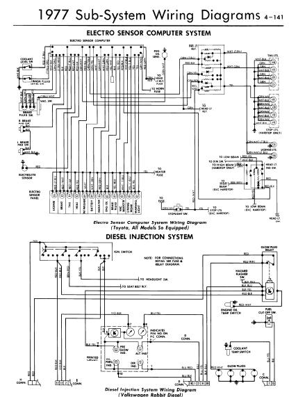
0 1977 Electro Sensor Computer System Wiring Diagrams

Manufacturer: Toyota
Models Covered: Toyota ( All Models 'SO' Equipped), Volkswagen Rabbit Diesel
Year: 1977


1 Page Wiring Diagrams


File Size: 76 KB
File Type: PDF

Thursday, March 25, 2010

0 Volkswagen Passat 1995 - 1997 Repair Manual

Make: Volkswagen
Model: Passat

Contents:
  • General and Technical Data
  • Front and Rear Suspension
  • Wheels and Tire Management
  • Anti-lock Brake System
  • Brakes - Mechanical and Hydraulic
  • Steering


Size: 11MB
File Type: PDF

0 Volkswagen TDI 1.9 Industrial Engine

Volkswagen TDI 1.9 litre Industrial Engine Workshop and Service Repair Manual


Contains the repair of TDI 1.9 litre engine

Contents:
  •  Combustion process
  • Injectors
  • Needle Lift Sender
  • Air-mass Flow Meter
  • Modulating piston movement sender 
  • Installation position
  • System overview
  • Fuel regulation
  • Injection commencement control
  • Exhaust gas recirculation
  • Charge pressure control
  • Glow plug system
  • Emission characteristics
  • Internal functions in the control unit
  • Self-diagnosis
  • Performance diagram
  • Specification
File Size: 934KB
File Type: PDF

Tuesday, March 23, 2010

0 Volkswagen Golf And Jetta Service and Repair Manual

DOWNLOAD VW Golf and Jetta Service and Repair Manual
Size: 7.86MB

Models Covered:
VW Golf and Jetta Mk 2 models with petrol engines, including fuel injection, catalytic converter
Formel E, 16-valve adn special/limited edition models 1043 cc, 1272cc, 1595cc & 1781 cc

Covers mechanical features of Van. Does not cover Convertible Rallye, Caddy, diesel engine, 4-wheel drive Mk 1 models or new Golf range introduced in February 1992.

Contents:
  • Roadside Repairs
  • Weekly Checks
  • Lubricants and fluids
  • Capacities and tyre pressures
  • Maintenance
  • Routine Maintenance and Servicing
  • Repairs and Overhaul
  • Transmission
  • Brakes and Suspension
  • Body Equipment
  • Wiring Diagrams
  • Reference
 

2012 BY ManualTransformerOnline Manual Sharing