Showing posts with label Opel. Show all posts

Friday, August 3, 2012

0 Opel 1968-77 Drive Axle Repair Manual

DESCRIPTION
Rear axle is a semi-floating integral carrier type. Axles are carried by ball bearings located on outer ends of each axle shaft. Removable housing cover permits inspection and service of differential. A breather fitting is located on top of the right axle tube.
AXLE RATIO & IDENTIFICATION
Opel uses only one basic type of axle assembly. Any differences in Removal & Installation or Overhaul procedure will be noted where they occur. To determine axle ratio, divide number of ring gear teeth by number of pinion gear teeth.
REMOVAL AND INSTALLATION
AXLE SHAFT AND BEARINGS
Removal - Raise and support rear of vehicle and remove wheel and brake drum. Unscrew rear axle shaft retaining plate. Using suitable axle shaft puller (J-8805) and slide hammer (J-2619) on axle flange, remove axle shaft. To remove bearing, cut off retaining ring using a chisel. Press off bearing using a suitable remover (J-22912).
Installation - Check radial runout of axle shaft at ball bearing seat and lateral runout of axle shaft flange near largest diameter. If axle shaft exceeds specifications for runout or is otherwise damaged, it must be replaced. Using suitable installer tool (J-21694-1), press on bearing so that oil seal groove on bearing faces shaft splines. Using an installer ring, press on retainer ring so that shoulder faces bearing.
AXLE ASSEMBLY
Removal and Installation - Raise rear of vehicle and remove rear wheels and one brake drum. Disconnect parking brake components, lower shock absorber mounts, left end of track rod and stabilizer bar shackles (if equipped). Disconnect universal joint from pinion flange and support or tie propeller shaft out of way after marking for reassembly. Disconnect brake lines. Lower axle assembly far enough to remove coil springs. Remove central support bracket and disconnect lower control arms. Remove axle assembly. To install, reverse removal procedure.
OVERHAUL
DISASSEMBLY
NOTE - Overhaul may be accomplished with axle assembly installed in vehicle.
Case Assembly - 1) Remove differential cover bolts and allow lubricant to drain. Disconnect left end of track rod and tie out of way. Remove rear wheels and brake drums. Remove axle shafts as previously described. Check and record ring gear backlash.
2) Mark differential side bearing caps and carrier so that caps can be reinstalled in original positions. Remove bearing caps. Using two wooden hammer handles, pry differential case assembly from carrier. Do not drop or interchange side bearing outer races. Insert suitable adapter (J-2241-11) in bearing hub and remove side bearings using suitable puller (J-22599) with adapter leg (J-22929)
3) Remove differential case-to-ring gear bolts and top ring gear off case using soft faced hammer. Remove differential pinion shaft retaining pin using a suitable pin punch. Remove pinion shaft, gears, side gears and thrust washers.
Drive Pinion - Remove torque tube assembly. Using suitable tool (J-229-32), hold barrrel spline and remove pinion preload nut. With the aide of above tool, remove barrel spline from drive pinion and remove pinion by tapping rearward with a soft face hammer. Remove rear pinion bearing using suitable tool (J-22912) and remove pinion bearing outer races using a brass drift.
Fig. 1 Exploded View of Opel Rear Axle Assembly

REASSEMBLY AND ADJUSTMENT
Fig. 2 Pinion Gauge Plate Installation
NOTE -  Prior to reassembly, all parts should be cleaned and inspected for imperfections.
Pinion Depth and Bearing Prelaod - 1) To determine the correct pinion depth setting, use the following procedures. Make sure all gauge parts are clean. Lubricate front and rear pinion bearings and position them in carrier. Thread stud (J-21772-43) into gauge plate (J-23597-22). Holding bearings in place, install gauge plate and stud assembly on rear pinion bearing, then install pilot (J-23597-21) on front pinion bearings.
2) Install nut on stud. Hold stud stationary with wrench and tighten nut until a reading of 20 INCH Lbs. is obtained when rotating gauge plate assembly with torque wrench.
3) Install discs on gauge shaft assembly, then position assembly in carrier so dial indicator rod is centered on gauge block and discs are seated in side bearing bores. Install bearing caps and tighten bolts to 35 Ft. lbs.
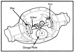
Fig. 3 Gauge Shaft Assembly Installed in Carrier
4) Set dial indicator at ZERO, then place on mounting post of gauge shaft with contact button touching the indicator pad. Push dial indicator down until needle rotates approximately 3/4 turn clockwise, then tighten indicator.
5) Rotate gauge shaft slowly back and forth until dial indicator shows the greatest deflection. At this point set indicator to ZERO. Repeat this operation to verify setting.
6) Now rotate gauge shaft until dial indicator rod does not tough gauge block and record reading at this point. The dial reading will show the thickness of the shim to be installed.
7) Select correct pinion shim in the following manner: Note number stamped on the head of drive pinion. This number indicates the necessary change in pinion mounting distance. If the number is plus, decrease the shim thickness. If the number is minus, increaes the shim thickness. No number indicates the pinion is nominal.
Fig. 4 Pinion Gear Reference Number
8) After establishing the correct pinion number, convert the figure from hundredth millimeters to inches. If the number is plus, subtract from the number arrived at in step 7). If the number is minus, add to the number in step 7). Use the Pinion Depth Code number chart to select the proper shim(s)
9) Remove all measuring tools, then place shim(s) on drive pinion. Press rear pinion bearing onto pinion using suitable installer J-21022.
10) Lubricate pinion bearings and assemble drive pinion collapsible spacer, front pinion bearing, oil deflector plate and barrel spline sleeve in differential carrier. Thread barrel spline sleeve installer (J-22938) onto drive pinion and draw spline sleeve onto pinion until there are sufficient threads of pinion protruding to install pinion preload nut. Do not use installer to adjust pinion preload.
11) Remove installer and install washer and pinion preload nut. Using suitable tool (J-22932) to hold barrel spline, tighten preload nut until specified preload torque is obtained. If preload specification is exceeded, replace collapsible spacer and adjust again. Use suitable tool (J-22931) to install a new pinion seal that has been soaked in rear axle lubricant. 
Fig. 5 Measuring Side Gear Play
Differential Case - 1) Install side gears and thrust washers. Lubricate and install pinion gears 180 degrees apart, and rotate gears as an assembly until pinion gear bores are aligned with the pinion shaft bores in the case. Install pinion shaft.
2) Using a dial indicator, measure the amount of backlash between side gears and pinion gears. Hold one side gear stationary while making check. If backlash exceeds .003" (.008 mm), make adjustments with thrust washers. Thrust washers are available in thickness to decrease backlash or decrease washer thickness to increase backlash.
3) Install lock pin into pinion shaft and caulk pin end to prevent loosening. Install ring gear on case and tighten bolt to specification. Check lateral runout of installed ring gear. If runout exceeds .003" (.008 mm), check for dirt or burrs holding ring gear in cocked position or that bolts are evenly tightened.
Backlash & Side Bearing Preload - 1) Install side bearings using suitable installer (J-22919) and drive handle (J-8092) while supporting opposite side of case on pilot (J-2241-11) to prevent bearing damage.
Fig. 6 Measuring Side Bearing Preload
2) Position differential case assembly, less side bearing shims, into side bearing bores of carrier. Insert feeler gauges of sufficient thickness between each bearing outer race and carrier to remove all end play. Ensure feeler stock is pushed to bottom of bearing bores. Mount suitable dial indicator (J-8001) on carrier so indicator stem is at right angles to a tooth on ring gear. Adjuster feeler gauge thickness from side to side until ring gear backlash is to specifications.
3) With zero end play and correct backlash established, remove feeler gauges, determine thickness of shims required an add .002" (.05 mm) to each shim pack to provide side bearing preload. Remove case assembly and install shim packs with respective side bearing using suitable installer (J-22919), driver handle (J-8092) and pilot (J-2241-11). Position case assembly and outer races in carrier. Use a soft faced hammer to drive case into carrier until side bearing outer races bottom in their bores.
4) Install side bearing caps in their original locations and tighten bolts. Rotate case assembly several times to seat bearings. Check backlash and preload using a torque wrench on ring gear attaching bolt. If torque is not correct, it will be necessary to re-shim side bearings. Install torque tube assembly and axle shaft.

Sunday, January 22, 2012

0 Opel 1974 Wheel Alignment Repair Guide

OPEL SPECIFICATIONS AND ADJUSTMENTS

TIRE INFLATION (COLD)
Before attempting to check or adjust wheel alignment, make sure tires are properly inflated. Refer to manufacturer's specifications given in owner's manual.

CASTER
All Models - If caster angle is not to specifications, adjust by changing shims on upper control arm shaft. Raise vehicle and place jack stands under lower control arms. Remove wheel on side which requires caster adjustment. Loosen hex nut from upper control arm shaft and remove shaft. Adjust caster by replacing shims on shaft between upper control arm shaft and chock absorber support. To reassemble, reverse disassembly procedure.

CAMBER 
All Models - Raise front of vehicle and place jack stands below lower control arms. Remove wheel on side to be adjusted. Remove ball joint from upper control arm and front steering knuckle. To adjust camber, lift upper control arm and rotate ball joint flange 180 degrees. NOTE - Only two adjustments are possible. Manufacturer adjusted camber to smallest possible negative camber. Rotating ball joint flange will make camber more negative. To reassemble, reverse disassembly procedure.

TOE-IN
All Models - 1) Position front wheel in straight ahead position. Remove clamp on tie rod bellows and push bellows back. Loosen tie rod clamping bolts. To adjust, rotate tie rod sleeves equally to obtain specified toe-in. NOTE - Never grip tie rod on inner ball joint stud. To avoid ball stud resting against inside of hole in tie rod outer end, center outer end of each rod to ball stud.

2) Pull bellows over tie rods and secure wire clamps. Bellows must not be twisted and wire ends showing towards steering ear adjusting screw opening. Tighten clam bolts. Rotate wheel back and forth several times to check bellows for correct attachment to tie rods.

0 Opel 1966-73 Wheel Alignment Repair Guide

1966-73 OPEL SPECIFICATIONS AND ADJUSTMENTS

TIRE INFLATION (COLD)
Before attempting to check or adjust wheel alignment, ensure that tires are properly inflated.


CASTER
All Models - 1) Raise front of vehicle and place jack stands below control arm (Manta and 1900) or below front frame side members (Kadett and GT). Remove wheel if caster is to be adjusted. Install suitable front spring compressor (J-21689) and compress spring (Kadett and GT only). Remove upper control arm shaft. Remove upper control arm for shock absorber support.

2) Adjust caster by changing shim between upper control and shock absorber support. Shims are available in .12", .24" and .36" thickness. To increase caster, place one .12" shim at front of control arm and one .36" shim at rear. To decrease caster, reverse shims. NOTE - Never use more than one shim at either location. The total thickness of front and rear shims combined must equal .48". Install control arm and shaft making sure crown of both shims shows inward. Remove spring compressor, replace wheel and lower vehicle. Recheck caster.

CAMBER
All Models - Raise front of vehicle and place jack stands below lower control arms. Remove wheel if camber is to adjusted. Remove ball joint from upper control arm and front steering knuckle. To adjust camber , lift upper control arm and turn ball joint flange 180 degrees. NOTE - Only two camber adjustments are possible. Manufacturer adjusted camber to smallest possible positive camber (Kadett and GT) and smallest possible negative camber (1900 and Manta). Rotating flange will make camber more positive on Kadett and GT or more negative on 1900 and Manta. To reassemble reverse disassembly procedures.

TOE-IN
Kadett (1966-72) and GT (1969-73) - 1) Position front wheels in straight ahead position. Remove wire clamps on left and right tie rods and push bellows back. Loosen tie rod clamp bolts. To adjust toe-in, rotate tie rod sleeves until toe-in within specifications. NOTE - Never grip tie rod on inner ball joint stud. To avoid ball stud resting against side of hole in tie rod outer end, center outer end of each tie rod to ball stud.

2) Pull bellows over tie rods and secure wire clamps. Bellows must not be twisted and wire ends showing forwards steering gear adjusting screw opening. Tighten clamp bolts. Rotate wheel back and forth several times to check bellows for correct attachment to tie rods.

1900 Models (1971-73) and Manta (1973) - Position front wheels in straight ahead position. Loosen and back off lock nuts on left and right tie rods. Remove hose clamps from bellows and adjust toe-in to specification by turning tie rods. NOTE - Do not allow bellows to become twisted. Tighten the rod lock nuts. Attach clamps and secure bellows to tie rods with clam bolt facing forward. Rotate wheel back and forth several times to check bellows for correct attachment to tie rods.


Wednesday, November 23, 2011

0 1965 Import Vehicles Ball Joint Checking Guide

ARROW / COLT

All Models - With components removed from control arm and ball joint still installed, check following: Horizontal and vertical free play (0"), and ball joint rotation starting torque 4-6 ft. lbs. (6-8Nm). Replace ball joints if correct specifications are not obtained

AUDI

Fox - Clearance of ball joint with pressure applied by leverage should be .04-.10" (1.0-2.5 mm). if not replace ball joints

BMW

All Models - With lower control arm removed, measure axial (up and down) movement of ball joint stud. If movement exceeds .0945", replace ball joint.

COURIER

All Models - Check working surfaces of ball joints and studs for wear or damage. End play should not exceed .031" (.8 mm), if end play is excessive, replace ball joint.

DATSUN

All Models (Exc. 620 Pickup) - Remove lower control arm. Use appropriate spring tension gauge and and attach it to top of ball joint stud nut. Measure force (INCH Lbs.) required to move ball joint stud laterally. If measurement is not within specifications, replace ball joint


FIAT

All Models - With vehicle raised and supported under lower control arms, grasp wheel at top and bottom and try to shake wheel. If any movement is noted, control arm must be removed for further inspection.

HONDA

All Models - Raise and support front of vehicle. Attach dial indicator onto lower control arm with indicator tip on steering knuckle near ball joint. Place pry bar between lower control arm and steering knuckle. NOTE - Take care not to damage ball joint rubber boot. Push on pry bar and observe movement on dial indicator. If movement is in excess of .020" (.5 mm), ball joint must be replaced.

JAGUAR

All Models - Upper ball joint must be replaced if signs of wear or play are evident. The lower ball joint is adjustable with shims if axial play exceeds .004-.006" (.10-.15 mm). Shims must not be removed to take excessive wear in ball pin and socket. If parts are excessively worn, replacement is required.

LANCIA

All Models - if ball joint shows excessive amounts of wear (play) replace ball joints.

LUV

With vehicle raised and supported under lower control arms, grasp wheel at top and bottom. Try to move wheel and replace ball joint if movement exceeds .06" (1.52 mm).

MAZDA

All Models - Check ball joint dust seal for wear or damage and if necessary, replace seal. Ball joint end play must not exceed .039" (1 mm). If end play exceeds specifications, replace ball joint

MERCEDES-BENZ

There should be no lateral movement of ball joint. Vertical movement is adjusted by adding or removing washers.

OPEL

All Models - Raise and support front of vehicle. Inspect ball joint rubber boots for damage and replace as necessary. If lower ball joint axial play exceeds .008" (2 mm), ball joint must be replaced.

PEUGEOT

All Models - When moving ball pin some friction torque should be felt. If ball pin can be moved without resistance end play is shown, replace ball joint.

RENAULT

All Models - Inspect ball joints for wear or excessive play. Replace ball joints as necessary.

SAAB

All Models - if ball joint exhibits excessive play, it must be replaced as a complete unit.

SUBARU

All Models - Check ball joint for excessive play by pushing and pulling on ball joint stud. Allowable looseness is less than .012". If play exceeds this specification, ball joint must be replaced.

TOYOTA

Corona and Pickup - To check lower ball joint, jack up lower suspension arm and check for ball joint looseness by moving wheel vertically and horizontally. Movement limit in vertical direction should be less than .04" (1 mm) Corona and .20" (5.0 mm) Pickup. Movement limit in horizontal direction should be less than .08" (2 mm). Corona and .09" (2.3 mm) Pickup.
NOTE -  Ensure other suspension parts are tight before checking ball joints. To check upper ball joints. disconnect upper suspension arm from steering knuckle. Turn ball stud and check for excessive looseness or tightness. Replace ball joint if it is excessively loose or tight.

All Other Models - Check for excessive looseness, proper operation and damaged ball stud. Replace as necessary.

TRIUMPH

All Models - Inspect ball joints for excessive wear or play. Replace ball joint as necessary.

VOLKSWAGEN

Type 1 - Raise front of behicle and turn steering to one side. Place pry bar tool over nut or bolt head mounting steering knucle to strut. Compress ball joint spring and place vernier caliper over top of ball joint and over bottom stud. Note caliper reading, then release lever and record caliper travel. Increase reading is ball joint play. Replace ball joints as necessary

Type 2 - Raise front of vehicle and turn steering to one side. Insert pry bar tool VW 281a (or equivalent) under lower control arm and over top of strut mounting. Fit a vernier caliper on lower or upper torsion arm and steering knuckle. Record measurement. Press down with lever and measure travel of vernier caliper. IF travel exceeds specifications, replace ball joint.

All Other Models - Raise and support, then turn steering to one side. Install suitable levering tool so that ball joint spirng may be compressed. With spring compressed, position a vernier caliper with lower jaw on ball joint stud and upper jaw on top of clamping bolt for ball joint stud. Note reading. Slowly release tension from spring and not travel of caliper. This reading indicates ball joint play. If specified play is exceeded replace ball joint.

VOLVO

All Models - Maximum permitted axial play for lower ball joint is 12" (3 mm). Check ball joint by prying back and forth with a bar. If specifications are exceeded, replace ball joints.


Saturday, November 19, 2011

0 1975 Vehicles Ball Joint Checking

ALFA ROMEO
All Models - Check working surfaces of ball pins and their seats, and ball joint studs for damage or wear. Axial play should not exceed specifications (.04"). Replace complete ball joint unit when indicated

BMW
All Models - With lower control arm removed, measure axial (up and down) movement of ball joint stud. If movement exceeds .0945", replace ball joint.

COLT
All Models - With components removed from control arm and ball joint still installed, check the following: Horizontal and vertical free play (0") and ball joint rotation starting torque 4-7 ft. lbs. (.6-1.0 mkg). Replace ball joints if correct specifications are not obtained

COURIER
All Models - Check working surfaces of ball joints and studs for wear or damage. End play should not exceed .031" (.8mm). If end play is excessive, replace ball joint.

DATSUN
All Models (Exc. 620 Pickup) - Remove lower control arm. Measure axial movement by lifting and depressing ball joint stud. Difference between these two measurements is axial movement. Using suitable spring tension gauge attached to top of ball joint stud measure force (INCH lbs.) required to move ball joint stud laterally. If either measurement is not within specifications, replace ball joint.
Ball Joint Specifications
  Application                      Axial                     Lateral INCH Lbs. (cmkg)
B210..................   .004-.012"(.1-.3 mm)..........................  52 (60)
610,710 and 280Z....    .004" (.1 mm)..............................   35 (40)

FIAT
All Models - With vehicle raised and supported under lower control arms, grasp wheel at top and bottom and try to shake wheel. If any movement is noted, control arm must be removed for further inspection

HONDA
All Models - Raise and support front of vehicle. Attach dial indicator onto lower control arm with indicator tip on steering knuckle near ball joint. Place pry bar between lower control arm and steering knuckle.

JAGUAR
All Models - Upper ball joint must be replaced. If signs of wear or play are evident. The lower ball joint is adjustable with shims if axial play exceeds .004-.006" (.10-.15 mm). Shims must not be removed to take up excessive wear in ball pin and socket. If parts are excessively worn, replacement is required.

LUV
With vehicle raised and supported under lower control arms, grasp wheel at top and bottom. Try to shake wheel and if any movement is noted, inspect front suspension for wear or damage.

MAZDA
All Models - Check ball joint dust seal for wear or damage and, if necessary, replace seal. Ball joint end play must not exceed .039" (1 mm). If end play exceeds specifications, replace ball joint.

OPEL
All Models - Raise and support front of vehicle. Inspect ball joint rubber boots for damage and replace as necessary. Using suitable gauge (J-23745) measure axial play. If axial play is more than .080" (2 mm), ball joint must be replaced.

PEUGEOT
All Models - Inspect ball joints for roughness or excessive wear. Replace ball joints as necessary.

PORSCHE
All Models - When moving ball pin some friction torque should be felt. If ball pin can be moved without resistance and end play is shown, replace ball joint.

RENAULT
All Models - Inspect ball joints for wear or excessive play. Replace ball joint as necessary.

SAAB
All Models - If ball joint exhibits excessive play, it must be replaced as a complete unit.

SUBARU
All Models - Check ball joint for excessive play by pushing and pulling on ball joint stud. Allowance loosness is less than .012". If play exceeds this specification, ball joint must be replaced.


Wednesday, November 16, 2011

0 Wheel Bearing Adjustment Guide

ALFA ROMEO
All Models - While rotating hub, tighten spindle nut to 18 ft. lbs. Loosen nut, then retighten to 7 ft. lbs. Back off on nut 1/4 turn and install cotter key. If slot in spindle nut does not align with hole in spindle, tighten nut until it is possible to insert cotter key. After cotter key is installed, ensure that bearing retainer plate can be easily rotated by insterting a screwdriver in plate holes

AUDI
NOTE - The following procedure can only be performed using special tools indicated.

Model 100 (Front) - 1) Raise and support front of vehicle. Remove lower wheel bolt and replace with special wheel bolt adapter (V-104) and special dial indicator (G-43). By means of retaining screw on special tool (V1-104), adjust dial indicator to pretensioned position of 1 millimeter.

2) Grasp wheel at front and rear. First push inward on front while pulling outward on rear, record dial indicator reading. Reverse this procedure and record dial indicator reading. Difference between these two readings is wheel bearing play. If play exceeds .04-.07 mm, adjustment will be necessary.

3.) Remove cotter pin and castle nut. If there was too much play, tighten spindle nut until play is within specifications. If there was insufficient play, remove wheel, spindle nut and its shim. Replace and tighten spindle nut. Using 1 millimeter feeler gauge, loosen spindle nut until it is possible to insert feeler gauge between spindle nut and wheel hub. Attach special hub puller (V-26) and withdraw hub until it is firmly in contact with spindle nut. Remove puller and retighten spindle nut until it is within specifications

Model 100 (Rear) - Raise and support rear of vehicle. Remove grease cup and one wheel bolt. Attach special dial indicator (30-43), using wheel bolt adapter (40-104) and attachment (10-22). Dial indicator activator foot should be pretensioned to 1 millimeter against the stub axle. Grasp wheel at front and rear. Move wheel on horizontal axis. If reading on dial indicator is not .02-.04mm, adjustment will be necessary. Adjust by loosening or tightening spindle nut

NOTE - Fox front wheel bearing is not adjustable. Torque stub axle nut to 13 ft. lbs.

Fox (Rear) - Remove grease cup, cotter pin and castle nut. Tighten spindle nut and loosen for adjustment. Adjust by lightly tightening spindle nut until plain washer (beneath spindle nut) can just be moved from side to side, using screwdriver. Thin adjustment will correspond to .0012-.0027" (.03-06 mm) wheel bearing play.

AUSTIN
Austin Marina - Raise and support vehicle so that front wheel is not touching ground. Remove grease cup and attach suitable magnetic base dial indicator with base on brake drum and actuating foot touching spindle. Bearing wobble should be from .001-.005". If adjustment is required remove cotter pin and slacken castle nut. Torque castle nut to 5ft lb. while spinning wheel. Stop wheel, slacken castle nut, and retighten castle nut, finger tight only. Reinstall cotter pin. NOTE - At minimum end-float figure given a considerable amount of movement will  be felt in the front wheel. Do not reduce end-float below .001".

BMW
2002 Models - While rotating wheel hub, tighten castle nut to 22-24 ft. lbs., then rotate hub at least two more times. Loosen castle nut until bearing end play is noticed. Tighten castle nut to maximum of 2.2 ft. lbs., then loosen nut to nearest hole an install cotter key. NOTE - After adjustment, slotted washer should move easily, without noticeable resistance.

3.0 Si and 530 i Models - While rotating wheel hub, tighten castle nut to 7 ft. lbs. Loosen castle nut approximately 1/4 turn. Insert screwdriver in recess of bearing retainer washer and ensure washer can be rotated easily. Install suitable gauge holder (BMW 00 2 500) on wheel hub and install dial indicator with tip touching front axle stub. Move wheel hub back and forth several times and check bearing end play. Adjust castle nut until bearing end play is .0008-.0024". NOTE - Set bearing end play as close to lowest limit as possible. Install cotter key.

CAPRI
All Models - Rotate wheel, hub and drum assembly while turning adjusting nut to 17-25 ft. lbs. Back off nut one-half turn. Retighten adjusting nut to 10-15 INCH lbs. Reinstall cotter pin and check front wheel rotation

COLT
All Models - Tighten adjusting nut to 14.5 ft. lbs. After seating bearing components, loosen nut to 0 ft. lbs. Now make final adjustment to 3.6 ft. lbs. After installing lock cap, insert cotter pin. NOTE - Do not loosen adjusting nut more than 15 degrees to align spindle holes.

COURIER
All models - While rotating wheel, hub and drum assembly, tighten adjusting nut to 17-25 ft. lbs. Back adjusting nut off 1/2 turn and retighten nut to 6-8 ft. lbs. Install new cotter key and check wheel rotation.

DATSUN
All models - Tighten spindle nut to torque specifications in following table. Spin wheel and retorque spindle nut. Loosen nut according to specifications in following table and then tighten to align cotter key hole. Insert cotter pin.

Wheel Bearing Adjustment
Application                        Torque                  Loosen
B210..................................22-25....................90 Degrees
Pickup................................22-25....................40 to 70 Degrees
All Other.............................18-22...................60 Degrees

Model 124 and 131 - While rotating hub, torque spindle nut to 14.5 ft. lbs. Completely loosen nut and retighten to 5 ft. lbs. Loosen nut 30 Degrees and stake collar of spindle nut into machined slot on spindle. Attach dial indicator with magnetic base on brake drum and actuating foot on spindle. Hub end play should not exceed .004". NOTE - When ever spindle nut has been removed it must be replaced with a new nut.

FIAT (Cont.)
Models 128 and X 1/9 - Tighten front and rear spindle nuts to 112 ft. lbs. When spindle nuts are properly tightened, stake collar of spindle nut into machined slot on spindle.

HONDA
All Models (Front) - Front wheel bearings are not adjustable. Torque front spindle nut to 87-130 ft. lbs. (Civic CVCC)

JAGUAR
All Models - While rotating hub, tighten nut until no end play is evident. Loosen nut 1 or 2 flats to line up cotter key and install cotter key. End play should be measured with a dial indicator and should be .002-.006". If not within specifications, adjust axle nut to correct end play.

LUV
All Models - While rotating wheel, tighten spindle nut to 22 ft. lbs. Turn hub through two or three turns and loosen nut until just finger tight. Check free play. Using a pull scale attached to wheel stud, measure turning torque; adjust nut until pull recorded on scale is 1.1 to 1-2.6 lbs. when wheel begins to rotate.

MAZDA
All Models - With vehicle raised and supported under lower control arms, measure amount of bearing preload using a pull scale hooked on hub bolt. Preload should be 1.3-2.4 lbs. (81600) or .9-2.2 lbs. (all other models). If not to specifications, adjust by tightening spindle nut until correct bearing preload is obtained. Align slot of spindle nut with hole in spindle and install new cotter key.

MERCEDES-BENZ
All Models - While rotating hub, tighten clamping nut until hub can just be turned. Loosen clamping nut and release bearing tension by striking steering knuckle spindle with plastic hammer. Using a suitable dial indicator, check wheel bearing end play. End play should be .0004-.0008". Adjust clamping nut until end play is within limits. Tighten socket bolt of clamping nut. Washer between outer bearing and clamping nut should rotate with light pressure applied to it.

MG
Midget - Raise front of vehicle and remove each wheel. Remove caliper assembly, but do not disconnect hydraulic brake hose. Support caliper to prevent damage to hose. Attach suitable dial indicator and measure runout of hub at outer edge of brake rotor. If runout exceeds .006" remove rotor and reposition on hub. Torque spindle nut to 46 ft lbs. and recheck runout.

MGB and MGB/GT - Raise front of vehicle and remove fron wheels. Using suitable dial indicator, measure hub end play. Correct end play is .002-.004". If not within specifications, remove spindle nut, washer and outer bearing. Add or remove shims behind outer bearing, until correct end play is obtained with spindle nut torqued to 40-70 ft. lbs.

OPEL
All Models - Raise and support front of vehicle. While rotating wheel, torque spindle nut to 18 ft. lbs. Back off spindle nut 1/4 turn. If slot in spindle nut and hole in spindle do not align, back off nut until they are aligned and insert cotter pin. Properly adjusted wheel bearing will exhibit small amount of end play

PEUGEOT
All Models - While turning wheel tighten spindle nut to 22 ft. lbs. Loosen and retorque nut to 7 ft. lbs. Lock nut in this position by staking nut collar into slot of spindle.

PORSCHE
All Models - Turn wheel and tighten clamping nut just enough to seat roller bearings. Loosen until tab washer can be easily moved in a lateral direction (by means of screwdriver) and no perceptible bearing play is felt when hub is moved axially. Tighten screw on clamping nut to specified torque and recheck adjustment.

RENAULT
All Models (Front) - Front wheel bearings are not adjustable. Torque front spindle nut to 145 ft. lbs.

All Models (Rear) - Install washer and lock nut. Tighten lock nut to 36 ft. lbs. (5 mkg) to seat bearings. Loosen lock nut completely, then tighten nut to 1.4-2.9 ft. lbs. (.2-.4 mkg) and lock nut in place by bending flange into slot of lock nut.

SUBARU
All Models (Front) - Front wheel bearing is not adjustable. Tighten spindle nut to 174 ft. lbs.

4WD Station Wagon (Rear) - Rear wheel bearings are not adjustable. Tighten spindle lock nut to 145 - 181 ft. lbs.


Saturday, November 5, 2011

0 1974 Vehicles Ball Joint Checking

ALFA ROMEO
All Models - Check working surfaces of ball pins and their seats, and ball joint studs for damage or wear. Axial play should not exceed specifications (.04"). Replace complete ball joint unit when indicated.

BMW
All Models - With lower control arm removed, measure axial (up and down) movement of ball joint stud. If movement exceeds .0945", replace ball joint. See BMW in SUSPENSION Section.

CAPRI
All Models - To check ball joint wear, raise vehicle and attach a dial indicator to a suitable fixed pivot, with stem on ball joint cap. Raise wheel independently of vehicle and note maximum dial gauge reading. If gauge reading is in excess of .098", ball joint should be replaced.

COLT
All Models - With components removed from control arm and ball joint still installed, check the following: Horizontal and vertical free play (0"), and ball joint rotation starting torque 4-7 ft. lbs. (.6-1.0 mkg). Replace ball joints if correct specifications are not obtained.

DATSUN
All Models (Exc. 620 Pickup) - Remove lower control arm. See Datsun in SUSPENSION Section. Measure axial movement by lifting and depressing ball joint stud. Difference between these two measurements is axial movement. Using suitable spring tension gauge attached to top of ball joint stud, measure force (ft. lbs.) required to move ball joint stud laterally. If either measurement is not within specifications, replace ball joint.

Ball Joint Specifications
Application                                      Axial                                      Lateral
                                                                                         INCH Lbs. (cmkg)
B210............................    .004-.012" (.1-.3mm)................................52 (60)
610 & 710....................   .004" (.1 mm) ...................................35 (40)
260Z.............................   .001-.024" (.03mm-.6mm).....................................

FIAT
All Models - With vehicle raised and supported under lower control arms, grasp wheel at top and bottom and try to shake wheel. If any movement is noted, control ar must be removed for further inspection. See Fiat in SUSPENSION Section.

HONDA
Raise and support front of vehicle. Attach dial indicator onto lower control arm with indicator tip on steering knuckle near ball joint. Place pry bar between lower control arm and steering knuckle. NOTE - Take care not to damage ball joint rubber boot. Push on pry bar and observe movement on dial indicator. If any movement is noted on dial indicator, ball joint must be replaced. See Honda in SUSPENSION Section.

JAGUAR
All Models (Exc. "E" Type Series 3) - Upper ball joint must be replaced if signs of wear or play are evident. The lower ball joint is adjustable with shims if axial play exceeds .004-.006". Shims must not be removed to take up excessive wear in ball pin and socket. If parts are badly worn, replacement is required.

"E" Type Series 3 - Upper and lower ball joints are adjustable by using shims to keep play within limits. Lower ball joint should have .004-.006" axial play and upper ball joint should have .004" axial play. Shims should not be removed to take up excessive wear in ball pin and socket. If parts are worn, replacement is required.

JENSEN-HEALEY
Raise front of vehicle and support under each lower control arm. Grasp wheel at top and bottom and try to shake wheel. NOTE - Do not confuse axial play of wheel bearing with worn ball joints. If any looseness is observed, ball joints should be replaced. See Jensen - Healey in SUSPENSION Section.

LUV
With vehicle raised and supported under lower control arms grasp wheel at top and bottom. Try to shake wheel and if any movement is noted, inspect front suspension of wear or damage.

MAZDA
All Models  (Exc. Pickup) - Check ball joint dust seal for wear or damage and, if necessary, replace seal. Check ball joint for wear or looseness by disconnecting each tie rod and attaching a pull scale to tie rod hole in spindle arm. If this measurement is not within 27-40 lbs. (12-18 KG) or 13-22 lbs. (6-10 kg) all other it will be necessary to replace ball joint.

Mazda (Pickup) - Check ball joint dust seal for wear or damage and, if necessary, replace seal. Ball joint end play is preadjusted at factory to be from 0-.08" (0-2 mm). If end play exceeds specifications, replace ball joint in its assembled form.

OPEL
All Models - Raise and support front of vehicle. Inspect ball joint rubber boots for damage and replace as necessary. Using suitable gauge (J-23745) measure axial play. If axial play is more than .080" (2 mm), ball joint must be replaced.


Thursday, October 20, 2011

0 Opel Calibra Repair Manual

Manufacturer: Opel
Model: Calibra
Year: 1990 to 1998


Contains the following information and repairs for:

  • Fuel and Exhaust Systems
  • Engine Electrical Systems
  • Clutch
  • Manual Transmission
  • Driveshafts
  • Braking System
  • Suspension and Steering
  • Bodywork and Fittings
  • Body Electrical

File Size: 90 MB
File Type: JPEG, RAR

0 Opel Vectra 88 to 95 Repair Manual

Manufacturer: Opel
Model: Vectra
Year: 1988 to 1995


Contains the following information and repairs for:

  • Dimensions and Weights
  • Conversion Factors
  • Buying Spare Parts
  • Vehicle Identification
  • General Repair Procedures
  • Jacking and Vehicle Support
  • Radio/Cassette unit Anti-Theft System
  • Tools and Working Facilities
  • MOT Test Checks
  • Fault Finding
  • Glossary of Technical Terms
  • Index
File Size:
File Type: PDF, RAR

0 Opel Astra_J Body Repair Manual

Manufacturer: Opel
Model: Astra_J
Year: 2011


Contains the following information and repairs for:

  • General Information
  • Body Hardware and Trim
  • Body Repair
  • Body Systems
  • Roof
  • Seatbelts
  • Seats
  • Restraints
  • Steering
  • Suspension
  • HVAC System


File Size: 32 MB
File Type: PDF, RAR

Saturday, March 20, 2010

0 Opel Kadett

MDOWNLOAD Opel Kadett Repair Manual

Contents:
  • Routine maintenance and servicing
  • OHV engine
  • OHC engines
  • DOHC (16-valve)
  • Cooling, heating and ventilation systems
  • Fuel and exhaust systems - carburettor models
  • Fuel and exhaust systems - fuel-injected models
  • Starting and charging systems
  • Contact breaker ignition system
  • Electronic (breakerless) ignition system
  • Suspension and steering
  • Body work and fittings
  • Body electrical systems
  • Wiring Diagrams
  • Index
 

2012 BY ManualTransformerOnline Manual Sharing